Használati útmutató Festo CPX-4AE-4AA-H
Festo nincs kategorizálva CPX-4AE-4AA-H
Olvassa el alább 📖 a magyar nyelvű használati útmutatót Festo CPX-4AE-4AA-H (3 oldal) a nincs kategorizálva kategóriában. Ezt az útmutatót 23 ember találta hasznosnak és 5 felhasználó értékelte átlagosan 4.8 csillagra
Oldal 1/3
CPX-4AE-4AA-H
Input module
Festo SE & Co. KG
Ruiter Straße 82
73734 Esslingen
Deutschland
+49 711 347-0
www.festo.com
Brief instruction | Assembly, Installation
8159920
2021-06b
[8159922]
Translation of the original instructions
© 2021 all rights reserved to Festo SE & Co. KG
1
About this document
1.1
Applicable documents
All available documents for the product
è
www.festo.com/sp.
The following documents contain extensive information:
•Operating instructions for analogue module CPX-4AE-4AA-H.è
•Description of the CPX system P.BE-CPX-SYS-....è
2Safety
2.1Safety instructions
–
Only use the product if it is in perfect technical condition.
–Observe labelling on the product.
–Take into consideration the ambient conditions at the location of use.
–
Prior to mounting, installation and maintenance work: Switch off power supply
and secure it from being switched back on.
–
Comply with the handling specifications for electrostatically sensitive devices.
–Seal unused connections with cover caps to achieve the required degree of
protection.
–
Use connection hardware with the required degree of protection.
–Store the product in a cool, dry environment protected from UV and corrosion.
Keep storage times short.
–The product may generate high frequency interference, which may require
interference suppression measures in residential areas.
2.2Intended use
The input module is intended solely for use in terminal CPX and terminal CPX-P of
Festo. The input module is referred to as an analogue module in this document.
–Operate the product only with suitable CPX bus nodes, see operating instruc-
tions for analogue module
è
1.1 Applicable documents.
–Use only permissible combinations of module components
è
Tab. 1 Permis-
sible combination of manifold block and interlinking block.
–Only use the product in original status without unauthorised modifications.
Only the conversions or modifications described in this and the further appli-
cable documents are permitted.
Interlinking blockManifold block
CPX-P-AB-4XM12-4POL
Manifold block
CPX-P-AB-2XKL-8POL
Metal designpermissiblepermissible
Polymer versionnot permissiblepermissible
Tab. 1:
Permissible combination of manifold block and interlinking block
2.3Training of qualified personnel
Work on the product may only be carried out by qualified personnel who can
evaluate the work and detect dangers. The qualified personnel have skills and
experience in dealing with electrical (open-loop) control technology.
3
Additional information
–Contact the regional Festo contact if you have technical problems
è
www.festo.com.
–Accessories and spare parts
è
www.festo.com/catalogue.
4Product overview
4.1Function
The analogue module with HART functionality provides analogue current inputs
and current outputs and enables the recording and further processing of analogue
current signals.
5Assembly
5.1Mounting the electronics module and manifold block
Requirements
–Supply voltage is switched off.
–The interlinking block is clean and free of foreign matter.
–
DIL switches are set
è
Tab. 2 DIL switch settings.
1
22
2
2
3
4
5
6
7
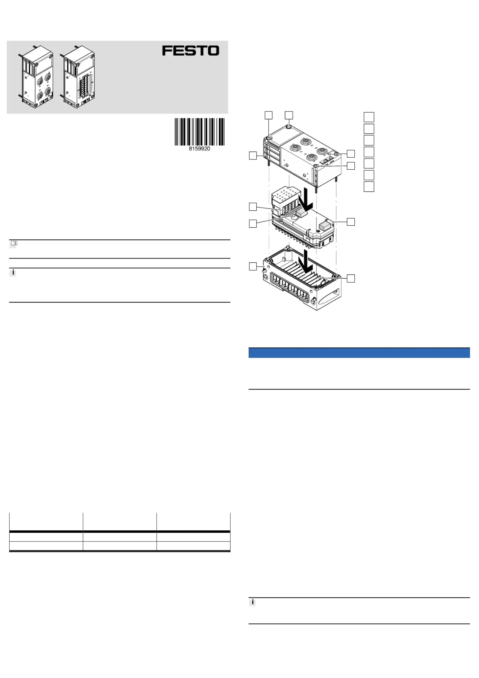
Fig. 1:Mounting of the electronics
module and connection block –
example
1
Manifold block
2
Screws T10
3
Electronics module
4
Busbars
5
Interlinking block
6
Coding pin
7
Plugs
Mounting the electronics module and manifold block
NOTICE
If threads are damaged or seals are defective, the device cannot achieve its
specified IP degree of protection.
Before mounting:
•Check the seals and thread. Replace damaged parts.
1.
Check seal and seal surfaces. Replace damaged parts.
2.
Place the electronics module in the interlinking block without tilting.
3.
Press the electronics module to the stop.
4.
Align the manifold block on the interlinking block with the electronics module.
5.Push the manifold block onto the interlinking block without tilting.
6.
Insert the screws and tighten them crosswise.
–Plastic interlinking block: use thread-grooving screws.
–Metal interlinking block: use screws with metric thread.
–
Tightening torque 0.9 … 1.1 Nm.
5.2
Dismounting the electronics module and manifold block
1.Switch off the power supply of the entire terminal CPX:
–Compressed air
–
Operating voltage for electronics and sensors
–Load voltage of valves
2.
Loosen the screws of the manifold block.
3.Pull the manifold block out of the plug of the electronics module without
tilting.
4.Pull the electronics module out of the contact rails of the interlinking block
without tilting.
6Installation
The connection of field devices on the analogue module depends on the type
of manifold block and setting of the DIL switches on the electronics module.
Information on installation Description of analogue module.è
6.1Power supply
The operating and load voltage supply is fed through interlinking blocks or end
plates (Protective Extra-Low Voltage, PELV) Description of system CPX.è
Termékspecifikációk
| Márka: | Festo |
| Kategória: | nincs kategorizálva |
| Modell: | CPX-4AE-4AA-H |
Szüksége van segítségre?
Ha segítségre van szüksége Festo CPX-4AE-4AA-H, tegyen fel kérdést alább, és más felhasználók válaszolnak Önnek
Útmutatók nincs kategorizálva Festo

30 Március 2025
30 Március 2025
30 Március 2025
30 Március 2025
30 Március 2025
30 Március 2025
30 Március 2025
30 Március 2025
30 Március 2025
30 Március 2025
Útmutatók nincs kategorizálva
Legújabb útmutatók nincs kategorizálva
10 Április 2025
10 Április 2025
10 Április 2025
9 Április 2025
9 Április 2025
9 Április 2025
9 Április 2025
9 Április 2025
9 Április 2025
9 Április 2025