Használati útmutató Festo HMIO-AP-2
Festo nincs kategorizálva HMIO-AP-2
Olvassa el alább 📖 a magyar nyelvű használati útmutatót Festo HMIO-AP-2 (2 oldal) a nincs kategorizálva kategóriában. Ezt az útmutatót 16 ember találta hasznosnak és 7 felhasználó értékelte átlagosan 4.2 csillagra
Oldal 1/2
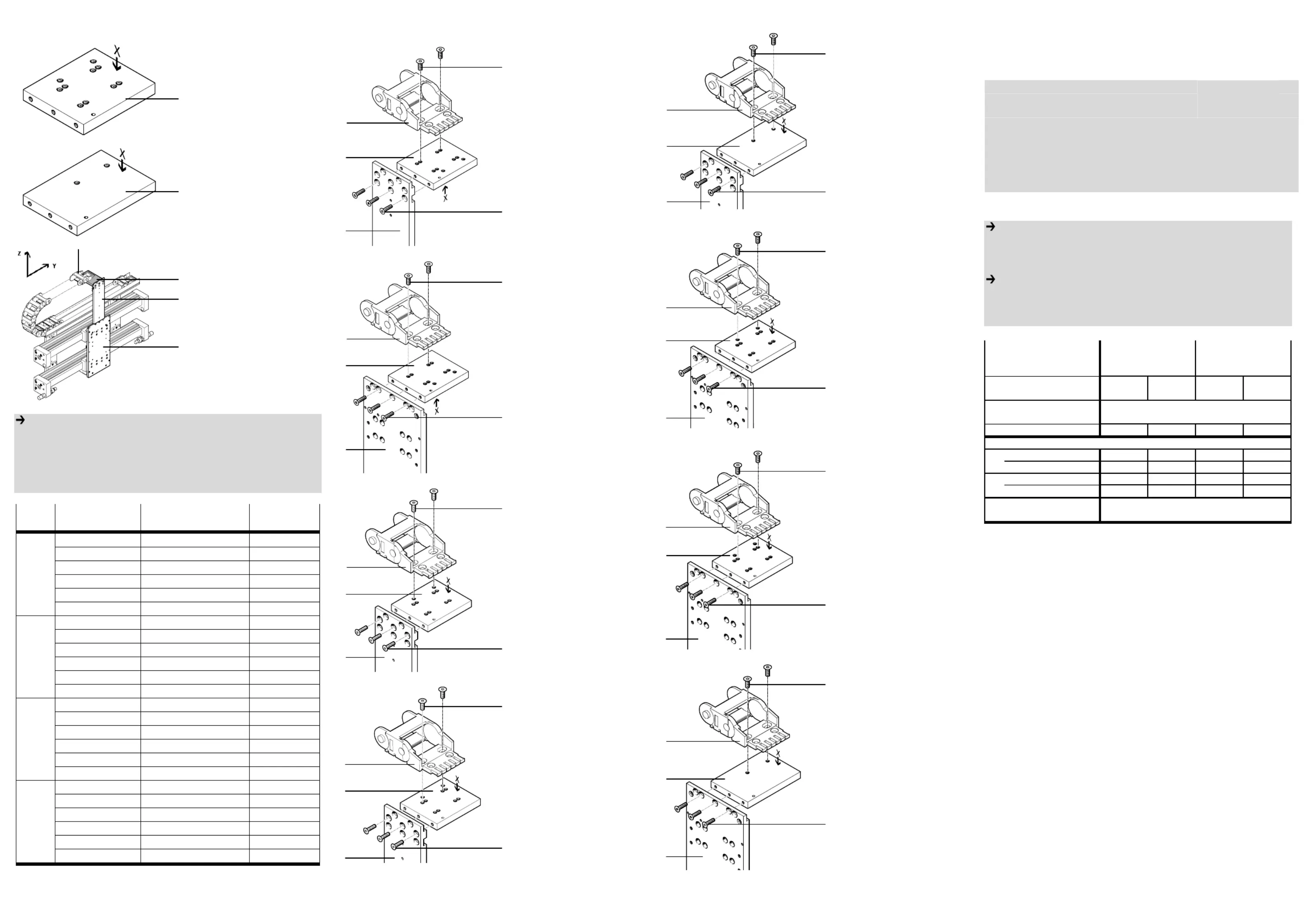
1. Installationsbausätze mit Montagebeispiel
1.a. HMIO-AP-1
1 In
stallationsbausatz
HMIO-AP-1 besteht aus
einer Wendeplatte
inklusive Befestigungs-
elemente A-B (siehe Ta-
belle).
1.b. HMIO-AP-2
2 I
n
stallationsbausatz
HMIO-AP-2
inklusive Befestigungs-
elemente A-B (siehe Ta-
belle).
1.c. Montagebeispiel
3 A
d
apterbausatz
HMVS-DL-...
4 Installationsbausatz
HMI..-LP
5 Energieführungskette
Bestimmungsgemäß dient
der Installationsbausatz
HMIO-AP-.. 1 bzw. 2 beim
Aufbau von Linienportalsys-
temen als Anbindungsplatte
der E-Kette 5.
Hinweis
• Montieren Sie den Bausatz HMIO-AP-... 1 bzw. 2 je nach Anbin-
dungsvariante. Die Anbindungsvarianten sind von der Ausführungsart
der Antriebsachse bzw. des Portalaufbaus (Mono- oder Duo-Bauweise)
abhängig. Die Zuordnung kann aus Tabelle 1 entnommen werden.
• Verwenden Sie nur zulässige Energieführungsketten laut Katalog.
Art Baukasten Antriebe Anbindungs-
varia
nte
HMBSY-LP-D25-1 DGE-25-SP-KF 2.a.
HMBSY-LP-D25-1 DGE-25-ZR-KF 2.a.
HMBSY-LP-D25-1 DGPL-25-KF 2.a.
HMBSY-LP-D25-2 DGC-25-KF 2.a.
HMBSY-LP-D25-3 DGPL-25-KF + SPC11 2.a.
Duo
BG 25
HMBSY-LP-D25-4 DGE-25-ZR-RF 2.a.
HMBSY-LP-M25-1 DGE-25-SP-KF 2.b.
HMBSY-LP-M25-1 DGE-25-ZR-KF 2.b.
HMBSY-LP-M25-1 DGPL-25-KF 2.b.
HMBSY-LP-M25-2 DGC-25-KF 2.b.
HMBSY-LP-M25-3 DGPL-25-KF + SPC11 2.a.
Mono
BG 25
HMBSY-LP-M25-4 DGE-25-ZR-RF 2.b.
HMBSY-LP-D40-1 DGE-40-SP-KF 2.c.
HMBSY-LP-D40-1 DGE-40-ZR-KF 2.c.
HMBSY-LP-D40-1 DGE-40-ZR-RF 2.d.
HMBSY-LP-D40-1 DGPL-40-KF 2.c.
HMBSY-LP-D40-2 DGC-40-KF 2.e.
Duo
BG 40
HMBSY-LP-D40-3 DGPL-40-KF + SPC11 2.c.
HMBSY-LP-M40-1 DGE-40-SP-KF 2.f.
HMBSY-LP-M40-1 DGE-40-ZR-KF 2.f.
HMBSY-LP-M40-1 DGE-40-ZR-RF 2.g.
HMBSY-LP-M40-1 DGPL-40-KF 2.f.
HMBSY-LP-M40-2 DGC-40-KF 2.h.
Mono
BG 40
HMBSY-LP-M40-3 DGPL-40-KF + SPC11 2.c.
Tabelle 1
2. Anbindungsvarianten (siehe Tabelle 1 und 2)
2.a. Duo-Systeme oder Mono-Systeme mit Messsystem der Baugröße 25.
1 In
stallationsbausatz
HMIO-AP-1
4 Installationsbausatz
HMI..-LP
5 Energieführungskette
•Befestigen Sie den Installa-
tionsbausatz 1 mit der
Seite X nach unten
1)
in der Nut am Installations-
bausatz 4.
•Befestigen Sie die E-Kette
5 an dem Bohrungspaar
wie abgebildet.
2.b. Mono-Systeme ohne Messsystem der Baugröße 25.
1 In
stallationsbausatz
HMIO-AP-1
3 Adapterbausatz
HMVS-DL-...
5 Energieführungskette
•Befestigen Sie den Installa-
tionsbausatz 1 mit der
Seite X nach unten
1)
an der Aussparung am
Adapterbausatz 3.
•Befestigen Sie die E-Kette
5 an dem Bohrungspaar
wie abgebildet.
2.c. Duo-Systeme oder Mono-Systeme mit Messsystem der Baugröße 40.
1 In
stallationsbausatz
HMIO-AP-1
4 Installationsbausatz
HMI..-LP
5 Energieführungskette
•Befestigen Sie den Installa-
tionsbausatz 1 mit der
Seite X nach oben
1)
oberhalb der
N
ut am Instal-
lationsbausatz 4.
•B
efestigen Sie die E-Kette
5 an dem Bohrungspaar
wie abgebildet.
2.d. Duo-Systeme mit DGE-40-ZR-RF.
1 In
stallationsbausatz
HMIO-AP-1
4 Installationsbausatz
HMI..-LP
5 Energieführungskette
•Befestigen Sie den Instal-
lationsbausatz 1 mit der
Seite X nach oben
1)
oberhalb der
N
ut am Instal-
lationsbausatz 4.
•Befestigen Sie die E-Kette
5 an dem Bohrungspaar
wie abgebildet.
2.e. Duo-Systeme mit DGC-40-KF.
2 In
stallationsbausatz
HMIO-AP-2
4 Installationsbausatz
HMI..-LP
5 Energieführungskette
•Befestigen Sie den Installa-
tionsbausatz 2 mit der
Seite X nach oben
oberhalb der Nut am Instal-
lationsbausatz 4.
•Befestigen Sie die E-Kette
5 an dem Bohrungspaar
wie abgebildet.
2.f. Mono-Systeme ohne Messsystem der Baugröße 40.
1 In
stallationsbausatz
HMIO-AP-1
3 Adapterbausatz
HMVS-DL-...
5 Energieführungskette
•Befestigen Sie den Installa-
tionsbausatz 1 mit der
Seite X nach oben
1)
an der
Aussparung am
Adapterbausatz 3.
•Befestigen Sie die E-Kette
5 an dem Bohrungspaar
wie abgebildet.
2.g. Mono-Systeme mit DGE-40-ZR-RF.
1 In
stallationsbausatz
HMIO-AP-1
3 Adapterbausatz
HMVS-DL-...
5 Energieführungskette
•Befestigen Sie den
Installationsbausatz 1 mit
der Seite X nach oben
1)
an der
Aussparung am A-
dapterbausatz 3.
•Befestigen Sie die E-Kette
5 an dem Bohrungspaar
wie abgebildet.
2.h. Mono-Systeme mit DGC-40-KF.
2 In
stallationsbausatz
HMIO-AP-2
3 Adapterbausatz
HMVS-DL-...
5 Energieführungskette
•Befestigen Sie den
Installationsbausatz 2 mit
der Seite X nach oben
an der Aussparung am A-
dapterbausatz 3.
•Befestigen Sie die E-Kette
5 an dem Bohrungspaar
wie abgebildet.
Hinweis
Nach der Montage:
• Verfahren Sie die Achsen von Hand und überprüfen Sie dabei die Instal-
lation bzw. das leichte Abrollen der Energieführungsketten.
Hinweis
• Beachten Sie:
-dass nur Befestigungskombinationen aus der Tabelle zulässig sind.
-zur Erdung, die Montageanleitung des Erdungsbausatzes.
Montageanleitung (de)
688604 / 2005-02NH
†‡
Installationsbausatz
HMIO-AP-...
Festo SE &G Co. K
Postfach
73726 Esslingen
++49/(0)711/347-0
www.festo.com
1
Installationsbausätze
Typ
Teile-Nr.
Anbaukomponenten
3434
3434
3434
34343434
Typ
HMVS-DL...HMI..-LPHMVS-DL40HMI..-LP
Anbaukomponente
Typ
Anbindungsvariante2.b. /f. /g.2.a. /c. /d.2.h.2.e.
Senkschrauben
M5x20 DIN 79913x3x3x3x
Senkschrauben
M6x16 DIN 79912x2x2x2x
M5M6
5,810
1) Bei Anbindung der Energieführungskette 5 aus entgegengesetzter
Richtung als abgebildet, wenden Sie die Platte des Installations-
bausatzes 1 entsprechend.
Gewinde
Befestigungselemente im Lieferumfang der Bausätze
540 121539 366
Tabelle 2
Anzugsdrehmomente in Nm
2
2
2
22
1
1
1
11
A
B
HMIO-AP-1HMIO-AP-2
E-Kette
5
5
5
55
2
1
-
2
3
4
5
5
1
4
B
A
5
1
3
B
A
5
1
4
B
A
A
B
5
1
4
5
2
4
A
B
1
3
5
A
B
5
1
3
A
B
5
2
3
A
B
Termékspecifikációk
| Márka: | Festo |
| Kategória: | nincs kategorizálva |
| Modell: | HMIO-AP-2 |
Szüksége van segítségre?
Ha segítségre van szüksége Festo HMIO-AP-2, tegyen fel kérdést alább, és más felhasználók válaszolnak Önnek
Útmutatók nincs kategorizálva Festo

30 Március 2025
30 Március 2025
30 Március 2025
30 Március 2025
30 Március 2025
30 Március 2025
30 Március 2025
30 Március 2025
30 Március 2025
30 Március 2025
Útmutatók nincs kategorizálva
Legújabb útmutatók nincs kategorizálva
10 Április 2025
10 Április 2025
10 Április 2025
9 Április 2025
9 Április 2025
9 Április 2025
9 Április 2025
9 Április 2025
9 Április 2025
9 Április 2025