Használati útmutató Festo SD-3-N
Festo
nincs kategorizálva
SD-3-N
Olvassa el alább 📖 a magyar nyelvű használati útmutatót Festo SD-3-N (2 oldal) a nincs kategorizálva kategóriában. Ezt az útmutatót 11 ember találta hasznosnak és 6 felhasználó értékelte átlagosan 4.8 csillagra
Oldal 1/2
Bedienungsanleitung Operating instructions
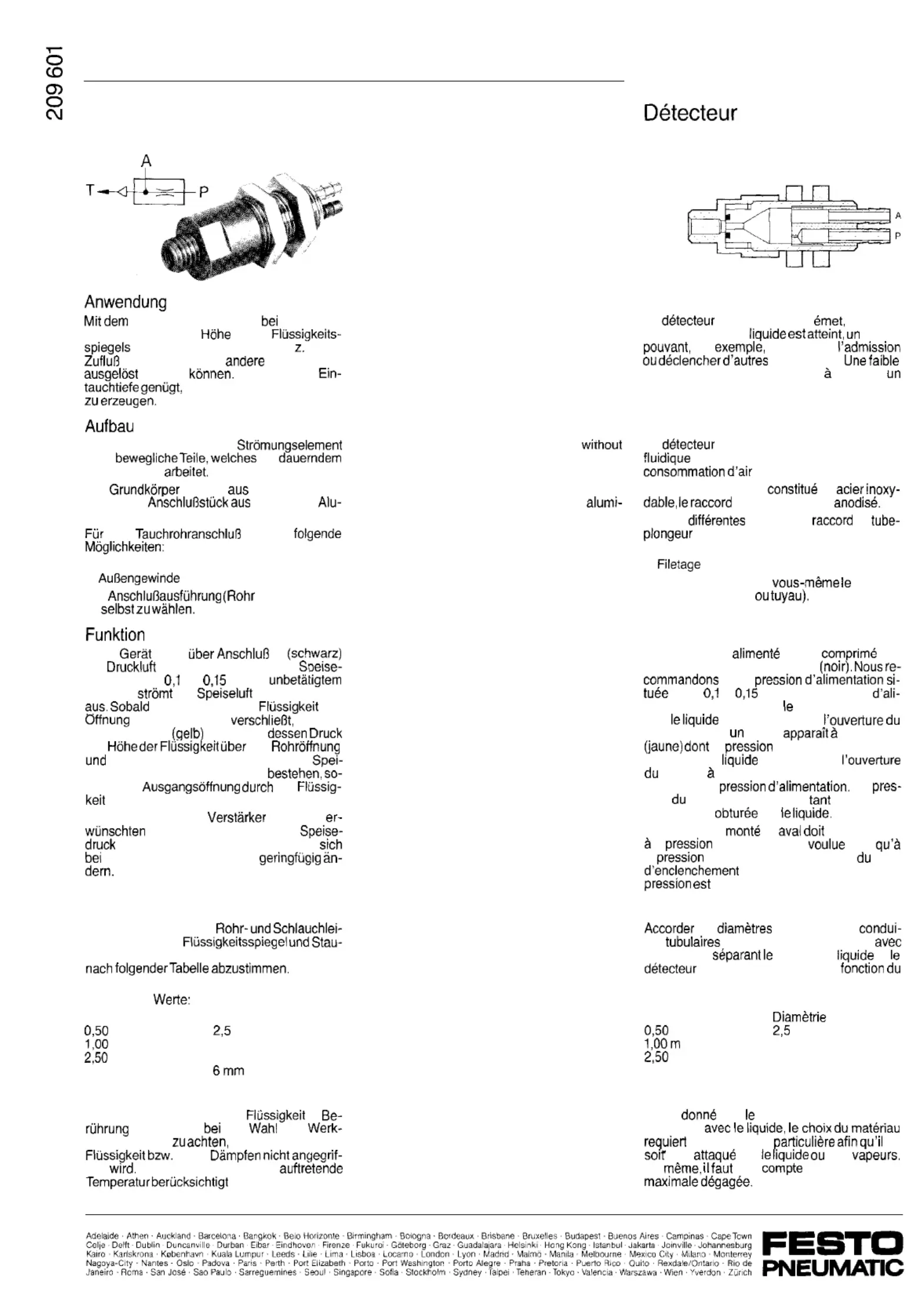
Staudruckgeber
Typ SD-3-N
Staudruckgeber wird
Erreichen
einer bestimmten
eines
ein Signal gegeben, mit dem
B. der
unterbrochen oder
Arbeitsgange
werden
Eine geringe
urn ein ausreichendes Signal
Der Staudruckgeber ist ein
ohne
mit
Luftverbrauch
Der
besteht nichtrostendem
Stahl, das
eloxiertern
minium.
den
gibt es
a) lnnengewinde M 5
b)
M 8
Die
bzw. Schlauch)
ist
D a s wird
P
mit
versorgt. Empfohlener
druckbereich
bis
bar. In
Zustand
die
am Tauchrohr
die ansteigende
die
des Tauchrohres
entsteht
am Ausgang A
ein Signal,
der
der
der Wichte proportional ist, bis zum
sedruck. Der Signaldruck bleibt
lange die
die
verschlossen ist.
Der nachgeschaltete
mu8 dem
Schaltdruck sowie dem
entsprechen. Der Schaltpunkt kann
Speisedruckschwankungen
Montage
Die Nennweiten der
tungen zwischen
druckgeber sind entsprechend der Entfernung
Empfohlene
Entfernung
Nennweite
m
mm
m
3mm
m
4mm
5,00 m
Hinweise
Da das Tauchrohr mit der
in
kommt, ist
der des
stoes darauf
da8 dieser von der
ihren
fen
Ebenso mu8 die max.
werden.
Level sensor
Type SD-3-N
Application
The level sensor provides a signal when a
liquid level has reached a specic height. This
signal can be used, e.g. for interrupting inow
of liquid or for initiating other operations. A
small immersed depth suces for generating
the suciently-strong signal.
The level sensor is a flow element
Design
moving parts which operates with a continuous
consumption of air.
The body of the device is made of stainless
steel, the connecting piece of anodized
nium.
For the dip tube connection the following are
available:
a) Internal thread M 5
b) External thread M 8
The type of connection (pipe or tubing) is to
be selected by the customer.
Operation
The device is supplied with compressed air via
port P (black). Recommended supply pressure
range 0.1 to 0.15 bar. In the non-operated
state, the supply air ows out through the dip
tube. As soon as the rising liquid closes the
opening in the dip tube, a signal is produced
at output A (yellow) with a pressure that ist
proportional to the height of the liquid above
the tube opening and to the specic gravity.
The maximum signal pressure is equal to the
supply pressure. The signal pressure is main-
tained as long as the outlet ist closed by the
liquid.
The downstream amplier must correspond to
the required switching pressure and supply
pressure. The switching point is subject to
minor changes dependent on uctuation in the
supply pressure.
Installation
The nominal width of the pipe and tubing lines
between the liquid level and the level sensor
should be determined from the following table
in accordance with the distance.
Recommended values:
Distance
Nominal width
0.50 m
2.5 mm
1 .OO m
3mm
2.50 m
4mm
5.00 m
6mm
Notes
Since the dip tube comes into contact with the
liquid, a suitable material must be chosen
which is not attacked by the liquid or its
vapours. Also, the maximum temperature which
can occur must be taken into account.
Instructions de service
de n de course
Type SD-3-N
Application
Le
de n de course
lorsqu’un
certain niveau de
signal
par interrompre
operations.
profondeur d’immersion suffit
produire
signal suffisant.
Construction
Le
de n de course est un element
sans pieces mobiles, travaillant par
permanente.
Le corps de base est
en
est en aluminium
II existe
versions de
de
a) Taraudage M 5
b)
M 8
Vous pouvez choisir
type de
raccordement (tube
Fonctionnement
L’appareil est
en air par
l’orifice de raccordement P
une
entre
et
bar. Au repos, l’air
mentation s’echappe par
tube-plongeur. Des
que
montant obture
tube-plongeur, signal
la sortie A
la
est proportionnelle a
la hauteur de au-dessus de
tube et
sa masse volumique pouvant
atteindre la
La
sion
signal est maintenue
que l’orice
de sortie est par
L’amplificateur
en
correspondre
la
de commutation
ainsi
la
d’alimentation. La variation
point
en cas de fluctuations de
insigniante.
Montage
les nominaux des
tes
et de la tuyauterie exible
la distance
niveau de
et
de fin de course en
tableau ci-joint.
Valeurs recommandees:
Distance
nominal
m
mm
3mm
m
4mm
5,00 m
6mm
Remarques
Etant
que
tube-plongeur entre en
c o n t a c t
une attention
ne
pas
par
ses
De
tenir
de la temperature
Termékspecifikációk
| Márka: | Festo |
| Kategória: | nincs kategorizálva |
| Modell: | SD-3-N |
Szüksége van segítségre?
Ha segítségre van szüksége Festo SD-3-N, tegyen fel kérdést alább, és más felhasználók válaszolnak Önnek
Útmutatók nincs kategorizálva Festo

30 Március 2025

30 Március 2025

30 Március 2025

30 Március 2025

30 Március 2025

30 Március 2025

30 Március 2025

30 Március 2025

30 Március 2025

30 Március 2025
Útmutatók nincs kategorizálva
- nincs kategorizálva Snow Joe
- nincs kategorizálva Altman
- nincs kategorizálva AVMATRIX
- nincs kategorizálva Vicks
- nincs kategorizálva GP
- nincs kategorizálva Davis
- nincs kategorizálva Staudte-Hirsch
- nincs kategorizálva Martin Audio
- nincs kategorizálva JAYS
- nincs kategorizálva King Canopy
- nincs kategorizálva Smit Visual
- nincs kategorizálva Nimbus
- nincs kategorizálva Jolin
- nincs kategorizálva SunBriteTV
- nincs kategorizálva Littelfuse
Legújabb útmutatók nincs kategorizálva

10 Április 2025

10 Április 2025

10 Április 2025

9 Április 2025

9 Április 2025

9 Április 2025

9 Április 2025

9 Április 2025

9 Április 2025

9 Április 2025