Használati útmutató Supermicro SuperServer SYS-112H-TN
Supermicro szerver SuperServer SYS-112H-TN
Olvassa el alább 📖 a magyar nyelvű használati útmutatót Supermicro SuperServer SYS-112H-TN (1 oldal) a szerver kategóriában. Ezt az útmutatót 24 ember találta hasznosnak és 6 felhasználó értékelte átlagosan 4.6 csillagra
Oldal 1/1
1
1
1
2
2
1
1
1
1
2
34
1234
1
2
34
56
12345
6
ItemtnDescripio
1P S 1owerupply
2P S 2owerupply
3
Dedicaedt BMC
LAN Ptor
4
Twoen U 3.2 GSB1
Ptsor
5A PtVGor
6UID Buontt
Imt tnteSloDescripio
PCIe 5.0 xM 16 AIO
Stlo
PCIe 5.0 x St 16lo
(FH, 6. L)6”
PCIe 5.0 x St 16lo
(FH, . L)123”
St 3 cat (FH, loloion
123”L). *
JFP1
MH5
SRW1
JPWR8
JPWR9
JIO1
J4
FAN5
FAN4FAN3
FAN2
JMCIO_PE8B1JMCIO_PE8A1
BAR CODE
BAR CODE
2242
2260
2280
22110
2242
2260
2280
22110
JSTBFAN
M.2_MH4
M.2_MH3
JTPM1
JRK1
M.2-C2
JNCSI1
JL1
DESIGNED IN USA
X14SBH
REV:1.01
BAR CODE
BAR CODE
BIOS LICENSE
2
J3
FAN10
JP2
JMCIO_PE7A1JMCIO_PE7B1
JPWR5
JPWR6
JPWR7
LED6
JBT1
J10
BT1
LED4
JNVI2C1
JBPNI2C1
FAN8
FAN7
FAN6
JMCIO_PE5A1
JMCIO_PE5B1
M.2-C1
M.2_MH1
M.2_MH2
P1 AIOM PCIe 5.0 x16
LED1
LED3
JAIOM1
FAN9
JMCIO_PE6B1
P1 SLOT 2
JMCIO_PE6A1
P1_PE4 8–15 VPP I²C
P1_PE4 0–7 VPP I²C
SRW2
FAN1
JNVI2C2
JBPNI2C2
JPWR10
JPWR11
JB1
JPT1
JB2
JPWR2
JPWR1
JPSU1
MH3
J35
CPU
DIMMD1
DIMMD2
DIMMC1
DIMMC2
DIMMB1
DIMMB2
DIMMA1
DIMMA2
DIMME2
DIMME1
DIMMF2
DIMMF1
DIMMG2
DIMMG1
DIMMH2
DIMMH1
BMC
JPSU2
JTIMED
JSXB0
CUT OUT
CUT OUT
CUT OUT
CUT OUT
CUT OUT
JROU1
JPFR3
JPFR1
JPFR2
JP1
JCP1
JSPD1
P1 SLOT1 PCIe 5.0 x16
JDBG1
J4CSBMSEL
JVRM1
JRSI2C1USB2/3
JAIOM2SB1
JPWR3
JPWR4
Rev. 1.0
Rev. 1.0
LBL-2758-T-QRG
LBL-2758-B-QRG
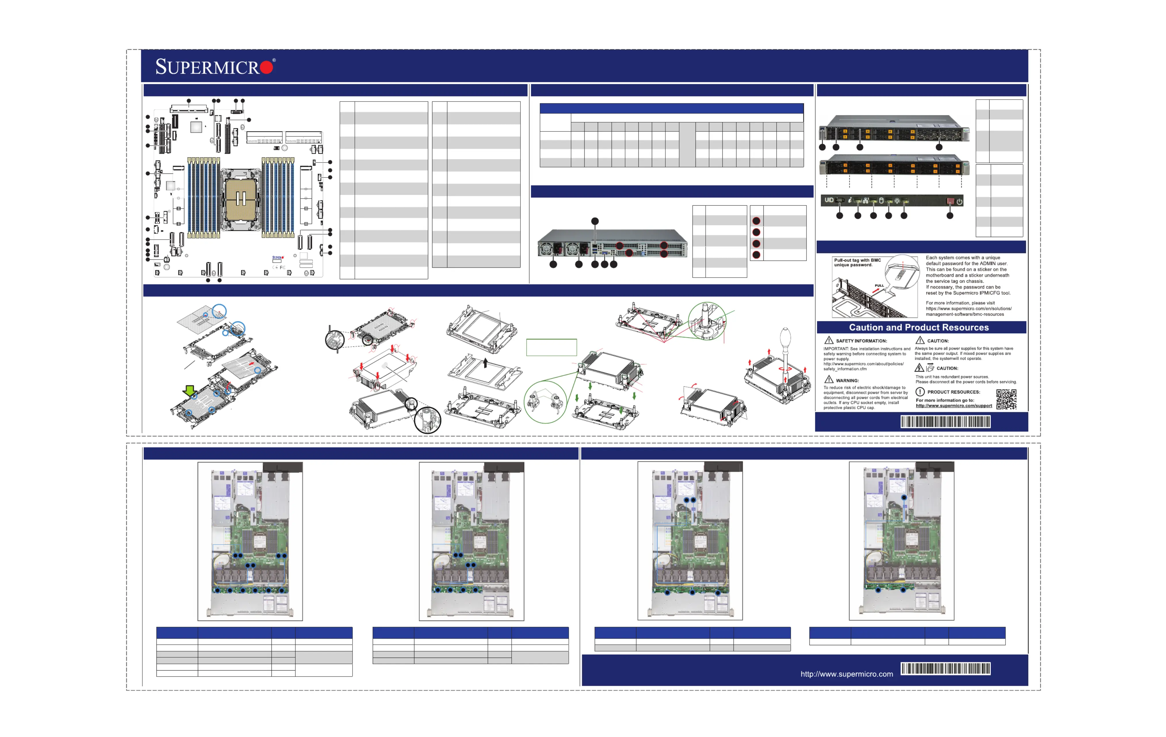
Rear View
System Information
CPU Installation, supporting a single Intel® Xeon® 6 Processor (LGA 4710)
Board LayoutMemory Support
NVMe Drive Cable RoutingStorage AOC Drive Cable Routing
SuperServer SYS-112H-TN Quick Reference Guide
8 NVMe
12 SAS
8 SAS
12 NVMe
BMC Label
No te:Please refer to user manual for memory module [rank] and [DRAM density] requirements when using Intel® Xeon® 6 CPU.
4
1
23
5
6
7
8
12
16
13
1415
10
11
9
18
19
17
20
21
22
24
25
26
27
23
ImtnteDescripio
1
JAIOM1: PCIe 5.0 x16lo AIOM St
Connector
2
PVME /131_N12: P 5.0 x8 Cle
MCConneor1_0-7IO ct (PPE6 )
3
PVME /151_N14: PCIe 5.0 x8
MCConneor1_8-15IO ct (PPE6 )
4JNCSI1: NC-SI rHeade
5JL1: Ints rruionHeade
6
P1 2SLOT: PCIe 5.0 St x164Clo
Connector
7
JRK1: Intel VROC RD Key AI
Header
8
M.22-C: M.2 PCIe 5.0 Intface er
(M-25key 11022/1102280/)
9: M orJM1TPTPConnect
10
PVME /191_N18: PCIe 5.0 x8
MCConneor1_8-15IO ct (PPE8 )
11
PVME /171_N16: P 5.0 x8 Cle
MCConneor1_0-7IO ct (PPE8 )
12
JN²CVI2: NVMe2CHeade I r
Channel 2
13
JB²CPNI2: N IBP2CHeade r
Channel 2
14
PVME 0/11_N: P 5.0 IO Clex8MC
Conneor1_ct (PPE4
)0-7
ImtnteDescripio
15
PVME 2/31_N: P x8 O Cle5.0MCI
Conneor1_8-15ct (PPE4 )
16
JN²CVI1: NVMe2CHeade I r
Channel 1
17
JB²CPNI1: N BPI2CHeade r
Channel 1
18: U 3.2 G r US/3B2SBen1Heade
19
PVME 6/71_N: PCIe 5.0 IO x8MC
Conneor1_8-15ct (PPE5 )
20
PVME 4/51_N: P x8 O Cle5.0MCI
Conneor1_0-7ct (PPE5 )
21
J1FP: Ft t Pl ronConrolane
Header
22: O BayBT1nboardCMOStter
23
M.12-C: M.2 PCIe 5.0 Intfe erac
(M-25key 11022/1102280/)
24
PVME /111_N10: P 5.0 x8 Cle
MCConneor1_8-15IO ct (PPE7 )
25
PVME 8/91_N: P x8 O Cle5.0MCI
Conneor1_0-7ct (PPE7 )
26
P1 1SLOT: PCIe 5.0 St x164Clo
Connector
27
J1IO: st Bd SyemI/Ooar
ConneorMCct ( U BVGA,SB, NIC)
DI eMMPopulionatGuid
Type
Chael nn
H1H2G1G2F1F2E1E2
CPU
A2A1B2B1C2C1D2D1
2 DIsMM
VV
4 DIsMM
VVVV
8 DIsMM
VVVVVVVV
16MM DIs
VVVVVVVVVVVVVVVV
A
Rotating Wire
1
2
Peek Nut
a
c
b
d
B. Assembling the Processor Heatsink Module (PHM)
1. If this is a new heatsink, the
thermal grease
has been preapplied.
Otherwise, apply the
proper amount of
thermal grease.
2. Hold the processor
carrier assembly so
the processor's gold
contacts are facing up,
then align the holes
of the processor
carrier assembly with the
holes on the heatsink.
Press the processor
carrier assembly down
until it snaps into place.
The plastic clips of the
processor carrier
assembly will lock at the
four corners.
3. Examine all corners to ensure
that the plastic clips on the processor
carrier assembly are firmly attached
to the heatsink.
A. Creating the Intel Xeon 6 CPU Carrier Assembly
1. Locate small gold triangle
(Pin 1) on processor
and corresponding
hollowed triangle
on carrier.
Pin 1
Make sure the lever
is pressed down before
installing the processor.
A
B
Pin 1
a
c
b
d
A
C
B
D
Processor Carrier Assembly
(Upside Down)
Triangle on the
processor carrier
Triangle on the CPU
Thermal grease
C. Preparing the CPU Socket for Installation
Gently pull off the plastic
protective cover by one
corner to remove it
from the CPU
socket.
D. Installing the Process Heatsink Module
1. Locate four threaded fasteners (a, b, c, d) on the CPU socket.
4. With a t30-bit screwdriver, tighten
all PEEK nuts in the sequence of
A, B, C, and D with even
pressure not greater than 8.0 in-lbf.
(0.904 N-m).
A, B, C, D: Peek Nut
1, 2, 3, 4: Rotating Wire
a, b, c, d: Threaded Fastener
Peek Nut
(Unlatched)
(Latched)
Rotating Wire
C
D
B
Rotating Wire
3
Rotating Wire 4
Rotating Wire
Grabsip T
a
b
c
d
(a, b, c, d: Threaded Fasteners)CPU Socket Pin1
Thadere
d
Feneast
r
CPU Socket
3. Press all four rotating wires outward to latch
the PHM onto the CPU socket.
Rotating
Wire
Rotating
Wire
2. Locate four PEEK nuts (A, B, C, D) and four rotating wires
(1, 2, 3, 4) on the heatsink as shown below. Gently place
the heatsink on the CPU socket, making sure that each
nut is properly aligned with its corresponding threaded
fastener.
A
B
C
D
2. Using the
triangles as a
guide, carefully
align and place
Point A of the
processor into
the carrier.
Gently snap into
place to
fasten onto
Point B.
2
3
1
46
5
A1
1
2
3
* Slot availability depends on system
configuration.
1
A1
2
3
Front View & Interface
23
1
4
67
5
8910
HDD 0HDD 2HDD 4HDD 6HDD 8HDD 10
HDD 1HDD 3HDD 5HDD 7HDD 9HDD 11
ImtnteDescripio
1U 3.0 PtSBor
2
Ft tl ronConro
Plane
3
Sviceet er/Ass
Tagwi th BMC
Pad sswor
Reset
4
StI/orage O
Bays
ImtnteDescripio
5
UID Bu / tton
B setMCRe
6
Infn ormatio
LED
7NIC LED
8 LEDHDD
9P LEDower
10P Buonowertt
Cor on onnect
BodarCard/
BackserDrveBaMCCaplane/Ri a rtndPoi yS blP/e N
P NVME0/1 (VMES11_CN1BPN-N5-H19N-8L0-L-MCIO-1330M5S)1CBL
P NVME2/3 (VMES11_CN2BPN-N5-H19N-8L2-L-MCIO-1330M5S)3CBL
P NVME4/5 (VMES11_CN3BPN-N5-H19N-8L4-S)5
CBFR-JL-MCIO-1464M5FB
P NVME6/7 (VMES11_CN4BPN-N5-H19N-8L6-S)7
P NVME/17 (VMES11_16CN1BPN-N5-H19N-4R8-S)9
CBFRFBL-MCIO-1439M5
P NVME/19 (VMES11_18CN2BPN-N5-H19N-4R10-S)11
Cor on onnect
BodarCard/
BackserDrveBaMCCaplane/Ri a rtndPoi yS blP/e N
P NVME0/1 (VMES11_CN1BPN-N5-H19N-8L0-L-MCIO-1330M5S)1CBL
P NVME2/3 (VMES11_CN2BPN-N5-H19N-8L2-L-MCIO-1330M5S)3CBL
P NVME4/5 (VMES11_CN3BPN-N5-H19N-8L4-S)5
CBFR-JL-MCIO-1464M5FB
P NVME6/7 (VMES11_CN4BPN-N5-H19N-8L6-S)7
Cor on onnect
BodarCard/
BackserDrveBaMCCaplane/Ri a rtndPoi yS blP/e N
SAS AOC CN1JSM1/JSM2 (BPN-NVME5-HS119N-S8L)7CBT0-L-SAS-1273L-10P0
SAS AOCCN2JSM1(BPN-NVME5-HS119N-S4R)11CBTP08-L-SAS-1262L-10
Cor on onnect
BodarCard/
BackserDrveBaMCCaplane/Ri a rtndPoi yS blP/eN
SAS AOC CN1JSM1/JSM2 (BPN-NVME5-HS119N-S8L)7CBT0-L-SAS-1273L-10P0
Termékspecifikációk
| Márka: | Supermicro |
| Kategória: | szerver |
| Modell: | SuperServer SYS-112H-TN |
Szüksége van segítségre?
Ha segítségre van szüksége Supermicro SuperServer SYS-112H-TN, tegyen fel kérdést alább, és más felhasználók válaszolnak Önnek
Útmutatók szerver Supermicro

12 Január 2025
12 Január 2025
11 Január 2025
9 Január 2025
29 December 2024
29 December 2024
29 December 2024
29 December 2024
29 December 2024
29 December 2024
Útmutatók szerver
Legújabb útmutatók szerver
9 Április 2025
3 Április 2025
2 Április 2025
29 Március 2025
29 Március 2025
29 Március 2025
24 Március 2025
24 Március 2025
15 Január 2025
15 Január 2025