Használati útmutató Whirlpool GMF 6422/IXL

Whirlpool sütő GMF 6422/IXL

Olvassa el alább 📖 a magyar nyelvű használati útmutatót Whirlpool GMF 6422/IXL (8 oldal) a sütő kategóriában. Ezt az útmutatót 11 ember találta hasznosnak és 6 felhasználó értékelte átlagosan 4.9 csillagra

Oldal 1/8
PRODUCT DESCRIPTION SHEET
EN
5019 300 02568
AU
To get full satisfaction from the hob, please read these instructions carefully and keep them for future consultation.
LIGHTING THE BURNERS
To ignite one of the burners, turn the relative knob anti-clockwise to the maximum flame setting .
Press the knob against the control panel to ignite the burner.
After the burner has ignited, keep the knob pressed for about 5 seconds to allow the thermocouple to warm up.
This burner safety device shuts off the gas supply to the burner if the flame goes out accidentally (because of sudden
draught, an interruption in the gas delivery, boiling over of liquids, etc.).
The device must not be pressed for more than 15 sec. If, after that time has elapsed, the burner does not remain lit,
wait at least one minute before trying to light it again.
- The burner might go out when the knob is released. This means that the thermocouple has not warmed up enough.
In this case, repeat the operations described above.
RACTICAL ADVICE FOR USING THE BURNERS
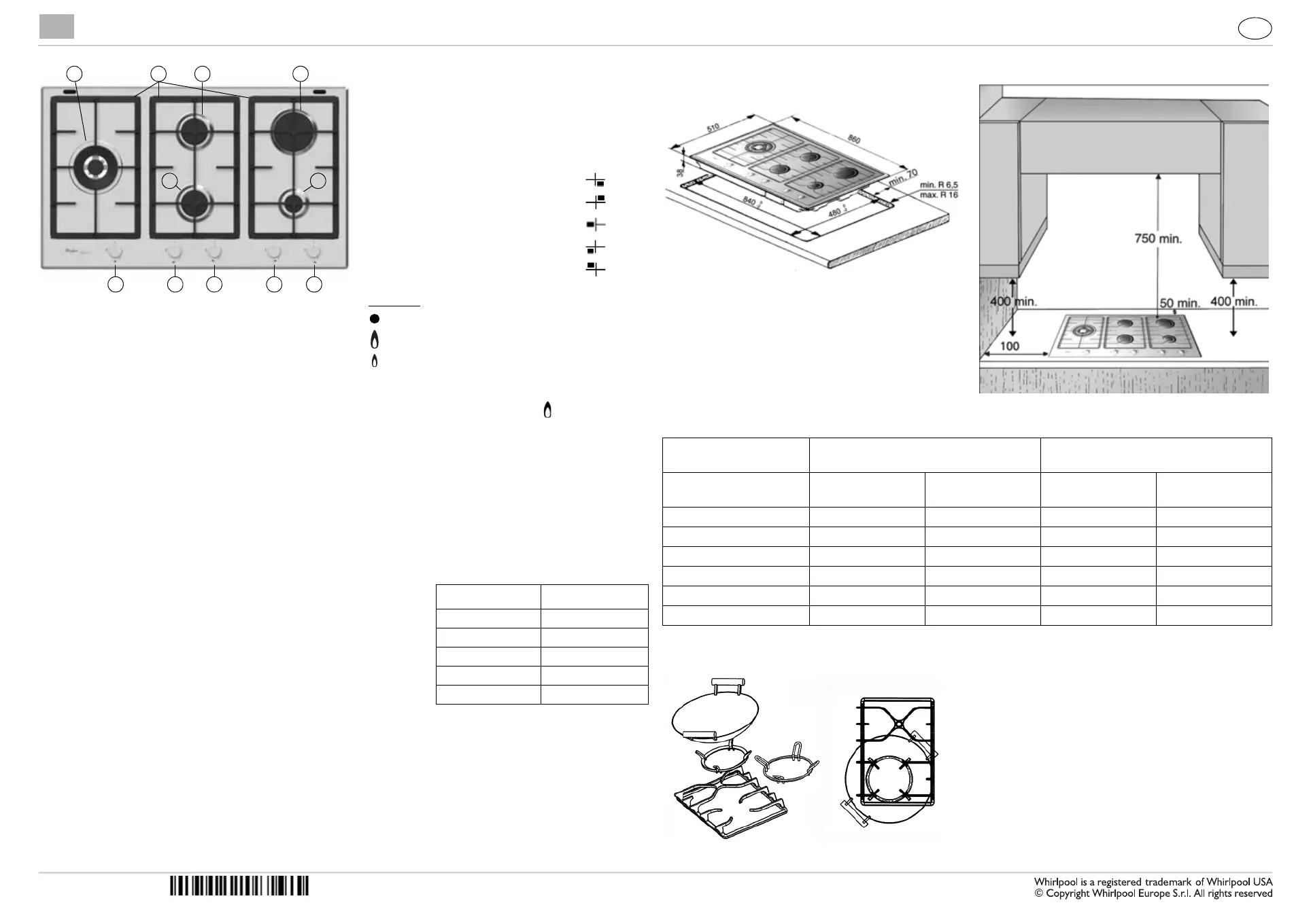
1. Removable panstand grids
2. Semi-rapid burner FC
3. Auxiliary burner
4. Semi-rapid burner BC
5. Rapid burner
6. 2 ring burner
7. Auxiliary burner control knob
8. Rapid burner control knob
9. 2 ring burner control knob
10. Semi-rapid burner FC control knob
11. Semi-rapid burner BC control knob
Symbols
Tap closed
Maximum flame
Minimum flame
32
78109
6
11
1 4 5
This hob has burners of different diameters. For better burner performance,
please stick to the following rules:
- Use pots and pans with bottoms the same width as that of the burners or
slightly larger (see table on the right).
- Only use flat-bottomed pots and pans.
- Use the correct amount of water for cooking foods and keep the pot covered.
- Make sure pots on the grates do not protrude beyond the edge of the hob
- In the case of pans with convex bottoms (WOK), use the support grille
(not included), which should be positioned only on the 2 ring burner.
IMPORTANT: improper use of the grids can result in damage to the hob: do
not position the grids upside down or slide them across the hob.
Do not use:
- Cast iron griddles, ollar stones, terracotta pots and pans.
- Heat diffusers such as metal mesh, or any other types.
- Two burners simultaneously for one receptacle (e.g. fish kettle).
Burner Pot Ø
2 ring From 24 to 30 cm
Rapid From 24 to 26 cm
Semi-rapid BC From 16 to 24 cm
Semi-rapid FC From 16 to 22 cm
Auxiliary From 8 to 14 cm
BC: means Back
Centre
FC: means Front
Centre
DIMENSIONS AND DISTANCES TO BE MAINTAINED (mm)
NOTE: In case of installation of a hood above the cooktop, please refer to the hood instructions for the correct distance.
NOTE: The indicated clearance dimensions are applicable to all non-combustible materials.
ELECTRIC SUPPLY: 220-240 V ~ 50/60 Hz 0.6 VA
WOK ADAPTER
Gas Type
Natural @ 1.00 kPa
(test point pressure)
Universal LP @ 2.75 kPa
(inlet pressure)
BURNER
Nominal Gas
Consumption (MJ/h)
Nominal Injector Size
(mm)
Nominal Gas
Consumption (MJ/h)
Nominal Injector Size
(mm)
FRONT RHS Auxiliary 4.1 0.90 3.4 0.52
REAR CHS Semi-Rapid C 6.8 1.17 5.5 0.67
FRONT CHS Semi-Rapid C 6.8 1.17 5.5 0.67
REAR RHS Rapid 9.6 1.40 9.5 0.85
MIDDLE LHS Wok C 17.6 1.92 15.0 1.08
TOTAL 44.9 - 38.9 -
PRECAUTIONS AND GENERAL ADVICE
To get full satisfaction from your hob, please read these instructions carefully and keep them for future consultation
These instructions are only valid for those Countries where the destination abbreviations are mentioned on the product
description sheet and on the hob.
Keep the packaging material (plastic bags, polystyrene parts, etc.) out of the reach of children, as they are potentially
dangerous.
Check whether the hob has been damaged during transport and remove any protective film from the appliance parts.
This hob (Class 3) is designed solely for household use for cooking food. Any other use (such as heating rooms) is to be
considered improper and, as a consequence, dangerous.
Ensure that the installation and gas/electrical connections are performed by a qualified technician in compliance with
current local safety regulations.
This appliance should only be installed and used in well-ventilated rooms, in accordance with current regulations.
Carefully read the instructions before installing and using this appliance.
Gas adjustment and supply pressure are indicated on the rating plate located under the hob. (Please, ensure the supplied
data label has to be attached in a suitable surface adjacent to the hotplate such as cupboard).
If the appliance is arranged for a type of gas different from that available, refer to the paragraph “Ajustment to different types
of gas”.
WARNING: DO NOT SPRAY AEROSOLS IN THE VICINITY OF THIS APPLIANCE WHILE IT IS IN OPERATION.
WARNING: ONLY APPLIANCE WITH SAFETY DEVICE BURNERS CAN BE INSTALLED IN MARINE CRAFT OR
CARAVANS. IN ANY CASE, IT SHALL NOT BE USED AS A SPACE HEATER.
WARNING: DO NOT USE OR STORE FLAMMABLE MATERIALS IN THE APPLIANCE STORAGE DRAWER OR
NEAR THIS APPLIANCE.
PROVISION FOR VENTILATION
ROOM VENTILATION
To ensure correct operation of the appliance, the room size in which it is to be installed shall be in accordance with AS5601.
This room must also be continuously ventilated, fresh air should flow through permanent openings in walls to outside or to an
adjacent non-inhabitable room as detailed is AS 5601. These permanent openings must be made in such a way that it cannot
be obstructed from either side of the wall, also they should be protected by plastic grids, metallic mesh, etc., taking care not
to reduce the air vent effective area mentioned above and located near floor level and positioned so as not to interfere with
the operation of the exhaust system, the minimum cross section of these permanent openings is set by AS6501 and shown in
Fig 1a,1b and 1c.
OVERHEAD CLEARANCE
Range hoods and exhaust fans shall be installed in accordance with the manufactures instructions. However, in no case shall
the clearance between the top of the highest burner of the cooking appliance and the range hood be less than 600 mm or, for
an overhead exhaust fan, 750 mm.
Any downward facing combustible surface less than 600 mm above the top of the highest burner shall be protected for the
full width and depth of the cooking surface area in accordance with Clauses 5.12.1.2 of AS 5601
However, in no case shall this clearance to any surface be less than 450 mm.
SIDE CLEARANCE
Where the distance measured between the periphery of the burner and any vertical combustible surface is less than 200 mm,
the surface shall be protected in accordance with Clause 5.12.1.2 of AS5601 to a height of not less than 150 mm above the
hotplate top surface for the full length and width of the cooking surface area.
Note: the cooking surface area is defined as the part of the appliance where the cooking normally takes place and does not
include those parts of the appliance containing the control knobs.
PROTECTING THE ENVIRONMENT
1. Packaging
The packaging material is entirely recyclable, and is marked with the recycling symbol , which identifies it as a type of
material that must be sent to local waste-disposal centres.
2. Product
The hob is made out of recyclable material. Before disposing of it, cut its power cable off in order to render it inoperative
and shut off the gas supply. Dispose of it in a waste-disposal centre in compliance with local regulations.
NOTES:
Improper use of the grids can result in damage to the hob surface. Do not position the grids upside down or drag them
across the hob.
In case of prolonged use, additional ventilation may be needed (opening a window or increasing the extraction force of
the hood).
This appliance is not intended for use by persons (including children) with reduced physical, sensory or mental
capabilities, or lack of experience and knowledge, unless they have been given supervision or instruction concerning use
of the appliance by a person responsible for their safety.
Keep children away from the hob when it is in use and do not let them play with the controls or any other appliance
parts.
Warning: the protective rubber feet on the grids represent a chocking hazard for young children. After removing the
grids, please ensure that all the feet are correctly fitted.
INSTALLATION
TECHNICAL INFORMATION FOR THE INSTALLER
This product can be embedded in a worktop 20 to 40 mm thick.
If there is no oven beneath the hob, insert a separator panel that has a surface at least equal to the opening in the work
surface. This panel must be positioned at a maximum distance of 150 mm below the upper surface of the work surface but,
in no case less than 20 mm from the bottom of the hob. In the case that you intend to install an oven beneath the hob,
make sure that it is equipped with a cooling system. The manufacturer declines all liability if another brand oven is installed
beneath the hob.
Before installation, make sure that:
- the local gas delivery conditions (nature and pressure) are compatible with the settings of the hob (see the rating plate
and injector table).
- The outer surfaces of the furniture or appliances adjacent to the hob are heat resistant according to local regulations.
- Combustion products are discharged outdoors through specific hoods or wall and/or window mounted electrical fans.
Min ventilation requirement for
air entry: 100 cm
3
Min ventilation requirement for air
entry: 100 cm
3
. As long as air
intake matches the capacity of the
air exhaust fan.
Min ventilation requirement for
air entry: 100 cm
3
Range hood
Fig. 1a Fig. 1b Fig. 1c
INSTALLATION
GAS CONNECTION
1. Check the “gas type” sticker attached to the hotplate. Details of the injector sizes used are recorded on the data plate
located on the base of the appliance.
2. This appliance shall be installed in accordance with installation requirements of the local gas authority of the appropriate
installation code. The gas supply system must comply with local regulations to the current relevant gas standard (AS/
NZS 5601 current edition).
3. Before installing the hotplate consider the location of the gas supply and routing the gas line. (Refer Fig. 1).
4. For ULPG models the gas supply for the hotplate must be regulated to a pressure of 2.75kPa. The gas inlet connection
fitting is ½” B.S.P male thread (in compliance with ISO 7 thread).
5. For NG models the gas supply is connected to a regulator which is supplied. The inlet connection has ½” B.S.P male
thread. IT IS ESSENTIAL THAT THE ELBOW ON THE APPLIANCE BE HELD FIRMLY WITH A SPANNER. DO NOT
OVER TIGHTEN. The regulated pressure for NG is 1.00kPa.
6. A manual shut-off valve must be installed in the gas line, in an accessible position external to the hotplate, so that in the
event of an emergency or service, the gas supply can be shutoff.
7. For gas inlet position of appliance refer Fig. 2 for NG and fig.3 for ULPG. After installing the gas supply and making all
connections check thoroughly for possible leaks. Turn all control knobs on the unit to “OFF” position. Open the valve
on the gas supply. Using a soap and water solution check each gas connection one at a time, by brushing the solution
over connection. Presence of bubbles will indicate a leak. Tighten the fitting and re-check for leaks. If it is not possible to
correct the leak, replace fitting. Under no circumstance use matches or flame for checking leaks.
8. Turn on appliance gas cock and light each burner. Check for a clear blue flame without yellow tipping. If burners shows
any abnormalties check the following:
- Burner cap on correctly
- Burner positioned correctly
- Burner vertically aligned with injector nipple
9. In some cases the burners will fail to ignite immediately and will seem to 'blow's lightly when they do ignite, this is usually
due to air in the gas pipe which should clear itself within seconds of operation.
10. If after following the instructions given, satisfactory performance cannot be obtained, contact the local gas authority for
advice and assistance.
WARNING: Appliance not suitable for connection with flexible hose assembly.
ELECTRICAL
CONNECTION
POINT
GAS CONNECTION
POINT
Fig. 1
Fig. 2
Fig. 3
ELECTRICAL CONNECTION
The electrical connections must comply with local
regulations.
The data relevant to the voltage and power
absorption are indicated on the rating plate.
The earthing of this appliance is compulsory by law.
The manufacturer cannot be held responsible for any injury to persons or animals or damage to property arising from
failure to comply with these requirements.
When the hob is installed, provide a single-pole circuit breaker with a contact separation of at least 3 mm.
If necessary, the electrical power cable must be replaced exclusively with a power cable having identical characteristics
to the original supplied by the manufacturer (type H05V2V2-F T90°C or H05RR-F).
This operation must be performed by a Qualified Technician or Authorised Person.
ASSEMBLY
After having cleaned the perimeter surface, apply the supplied gasket to the hob as
shown in the figure.
Position the hob in the worktop opening made respecting the dimensions indicated in the Product Description Sheet.
Note: the power supply cable must be long enough to permit its upward extraction.
To secure the hob, use the brackets (A) provided with it.
Fit the brackets into the relevant bores shown by the
arrow and fasten them by means of their screws in
accordance with the thickness of the worktop (see figures
on the right).
Earth
(yellow/green)
L
N
230 - 240 V
To p 4 0 m m
Top 30 mm
To p 2 0 m m

Termékspecifikációk

Márka: Whirlpool
Kategória: sütő
Modell: GMF 6422/IXL

Szüksége van segítségre?

Ha segítségre van szüksége Whirlpool GMF 6422/IXL, tegyen fel kérdést alább, és más felhasználók válaszolnak Önnek