Használati útmutató Crestron TST-600
Crestron nincs kategorizálva TST-600
Olvassa el alább 📖 a magyar nyelvű használati útmutatót Crestron TST-600 (2 oldal) a nincs kategorizálva kategóriában. Ezt az útmutatót 18 ember találta hasznosnak és 2 felhasználó értékelte átlagosan 4.1 csillagra
Oldal 1/2
Crestron Electronics, Inc.Installation Guide - DOC. 7687A
15 Volvo Drive Rockleigh, NJ 07647 (2041540)
Tel: 888.CRESTRON 12.14
Fax: 201.767.7576 Specifications subject to
www.crestron.com change without notice.
As of the date of manufacture, the TST-600-DS, TST-600-DSW, and TST-600-IMCW have been tested and
found to comply with specifications for CE marking.
Crestron TST-600 and TST-602
Accessories
Installation Guide
INTRODUCTION
This document provides installation instructions for accessories that ship with either the
TST-600 and TST-602 Wireless Touch Screens or the TST-600-WALL and TST-602-WALL
Wall Mount Wireless Touch Screens.
For installation instructions, refer to the section for each of the following accessories:
• TST-600-DS
• TST-600-DSW
• TST-600-FP and TST-600-FP-NB
• TST-600-IMCW
TST-600-DS INSTALLATION
The only connection to the TST-600-DS is via the fixed cable, which is connected to the TO
PANEL port on the (included) TST-600-IMCW Interface Module.
When connecting the TST-600-DS to the TST-600-IMCW, consider the following:
• Use Crestron® power supplies for Crestron equipment.
• The included cable cannot be extended.
Hardware Connection from the TST-600-IMCW to the TST-600-DS
To TO PANEL
Port on
TST-600-IMCW
NOTE: The length of the connecting cable on the TST-600-DS is 9 feet (2 3/4 meters).
The length of the cable has been shortened for illustrative purposes in the diagram above.
NOTE: The included cable mount ferrite bead, FBTH-2, should be placed on the cable
near the connector end.
1. Post-construction refers to framed walls with drywall hung.
2. Since the TST-600-DSW contains moving parts, mounting it to a stud offers more support and is
therefore highly recommended. Although Crestron offers the post-construction TST-600-DSW-WMKM
and TST-600-DSW-WMKT mounting options, a mouning option that is secured to a stud, such as the
TST-600-DSW-BB or TST-600-DSW-PMK, is highly recommended.
NOTE: There is also an international back box kit (TST-600-DSW-BBI) available for the
TST-600-DSW for installation in concrete and masonry. Refer to the TST-600-DSW-BBI
Installation Guide (Doc. 7454) at www.crestron.com/manuals.
If the TST-600-DSW-BB or TST-600-DSW-PMK is to be used and a TSW-600-DSW Docking
Station is not available, the installer can either leave the hole in the mounting surface open (if
permitted by local building codes) or attach the cover plate supplied with the mounting kit to
the mounting hole.
Installation
To install the TST-600-DSW, complete the following procedure in the order provided. The
only tool required is a #2 Phillips screwdriver.
CAUTION: Allow an air gap of at least 12 inches (305 mm) in the wall cavity above and
below the touch screen for heat dissipation.
NOTE: The TST-600-DSW has been optimized for mounting in 5/8” (~16 mm) drywall. A
thickness of 1/2” to 1” (13 to 25 mm) can be used without issue. Thinner or thicker drywall
causes issues with the installation of the product.
NOTE: The following steps are performed only after the TST-600-DSW-BB or
TST-600-DSW-PMK has been installed. It is assumed the TST-600-DSW-BB or
TST-600-DSW-PMK has been secured to the stud according to the instruction in the latest
installation guides (Doc. 7455 and Doc. 7453, respectively). It is assumed that drywall is in
place and a cutout for the TST-600-DSW and touch screen is made in the drywall.
The TST-600-DSW is shipped with the docking mechanism locked in its “back” position. In
order to make cable connections, the mechanism must first be unlocked so it slides to the
“forward” position. To do this, slide the release latch on the right side of the TST-600-DSW
upward to release the mechanism. The mechanism slides forward. To locate the release
latch, refer to “Undocking the Touch Screen.”
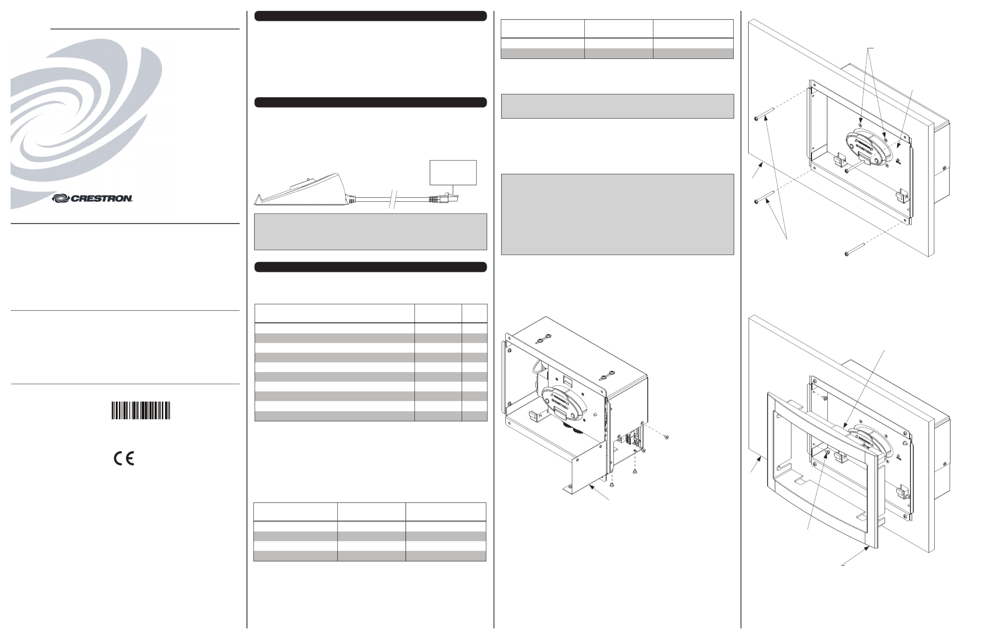
1. Remove the four screws holding the cover plate in place to gain access to the
connectors on the TST-600-DSW.
TST-600-DSW Installation (Cover Plate Removal)
Before mounting the unit into the wall, remove
the cover plate to access the connectors. Once
all cables are connected, replace the cover plate.
2. Hold the TST-600-DSW near the back box and connect the NET and LAN cables from
the back box to the ports on the back of the unit.
3. Replace the cover plate using the four screws from step 1.
4. Place the TST-600-DSW into the back box (or against the TST-600-DSW-PMK if using
this instead of the back box) and using the four supplied 06-32 x 1 1/2” screws, two at
the top and two at the bottom, to attach the TST-600-DSW to the back box as shown in
the following illustration.
Further Inquiries
To locate specific information or resolve questions after reviewing this guide, contact Crestron's True Blue Support at
1-888-CRESTRON [1-888-273-7876] or, for assistance within a particular geographic region, refer to the listing of
Crestron worldwide offices at www.crestron.com/offices.
To post a question about Crestron products, log onto Crestron’s Online Help at www.crestron.com/onlinehelp.
First-time users must establish a user account to fully benefit from all available features.
Future Updates
As Crestron improves functions, adds new features, and extends the capabilities of the TST-602-DS, TST-602-DSW,
TST-600-FP, TST-600-FP-NB, and TST-600-IMCW, additional information may be made available as manual
updates. These updates are solely electronic and serve as intermediary supplements prior to the release of a
complete technical documentation revision.
Check the Crestron website periodically for manual update availability and its relevance. Updates are identified as
an “Addendum” in the Download column.
Federal Communications Commission (FCC) Compliance Statement
This device complies with part 15 of the FCC Rules. Operation is subject to the following conditions:
(1) This device may not cause harmful interference and (2) This device must accept any interference received,
including interference that may cause undesired operation.
CAUTION: Changes or modifications not expressly approved by the manufacturer responsible for compliance could
void the user’s authority to operate the equipment.
NOTE: This equipment has been tested and found to comply with the limits for a Class B digital device, pursuant to
part 15 of the FCC Rules. These limits are designed to provide reasonable protection against harmful interference in
a residential installation. This equipment generates, uses and can radiate radio frequency energy and, if not installed
and used in accordance with the instructions, may cause harmful interference to radio communications. However,
there is no guarantee that interference will not occur in a particular installation. If this equipment does cause harmful
interference to radio or television reception, which can be determined by turning the equipment off and on, the user
is encouraged to try to correct the interference by one or more of the following measures:
● Reorient or relocate the receiving antenna
● Increase the separation between the equipment and receiver
● Connect the equipment into an outlet on a circuit different from that to which the receiver is connected
● Consult the dealer or an experienced radio/TV technician for help
Industry Canada (IC) Compliance Statement
CAN ICES-3(B)/NMB-3(B)
TST-600-DSW INSTALLATION
Supplied Hardware
The hardware supplied with the TST-600-DSW is listed in the following table.
Supplied Hardware for the TST-600-DSW
* Pre-construction refers to framed walls prior to hanging drywall.
1. These parts come with the TST-600-DSW-B-S (Smooth Black).
2. These parts come with the TST-600-DSW-B-T (Textured Black).
3. These parts come with the TST-600-DSW-W-S (Smooth White).
Mounting Options
The TST-600-DSW Docking Station and TST-600 or TST-602 Touch Screen install simply
and cleanly into existing or newly constructed wall with an assortment of pre- and
post-construction mounting options. All mounting options are sold separately from the touch
screen. Refer to the following table for a complete list of mounting options and respective
installation guides.
Pre-Construction Mounting Options for the TST-600-DSW and TST-600 or TST-602
PRE-CONSTRUCTION*
OPTION MODEL DOCUMENT NUMBER
Back Box Kit TST-600-DSW-BB 7455
Pre-Construction Mount Kit TST-600-DSW-PMK 7453
Mud Mount Kit (Accessory) TST-600-DSW-MMK 7457
Trim Mount Kit (Accessory) TST-600-DSW-TMK 7456
POST-CONSTRUCTION 1
OPTION MODEL DOCUMENT NUMBER
Wall Mount Kit - Mud TST-600-DSW-WMKM
2
7457
Wall Mount Kit - Trim TST-600-DSW-WMKT
2
7456
Post-Construction Mounting Options for the TST-600-DSW and TST-600 or TST-602TST-600-DSW Installation (Secure to the Mounting Option)
5. Use the four supplied 04-40 x 3/16” flat head screws to attach the aesthetic plate to the
front of the TST-600-DSW mechanism.
6. Push the mechanism backward into the box until it locks in place exposing the screw
holes on the left and right sides. Refer to the following illustration.
7. Install the bezel, being careful to orient it with the IR window facing up. Refer to the
following illustration.
TS-600-DSW Bezel Installation
Screws (4)
06-32 x 1 1/2”
NOTE: Either the TST-600-DSW-BB or TST-600-DSW-PMK
must be installed before installing the TST-600-DSW into the wall.
Wall
Secure the aesthetic plate to the
docking station assembly with the
four (4) included 04-40 x 3/16” screws.
Aesthetic Plate
Install the bezel with the
IR window facing up.
Secure the bezel to the metal chassis box
using the supplies screws and washers.
Screws (4)
06-32 x 3/16”
with Nylon Washers
Wall
8. Use the four supplied 06-32 x 3/16” screws with washers, two on the left side and two
on the right side, to attach the bezel.
9. Dock the TST-600 or TST-602. Refer to “Docking the Touch Screen’’ for details.
DESCRIPTION PART
NUMBER QTY
Assembly, Bezel, with IR, Wall Dock, Black14504777 1
Assembly, Bezel, with IR, Wall Dock, Textured Black2 4507641 1
Assembly, Bezel, with IR, Wall Dock, White34507241 1
Silkscreen, Assembly, Metal, Plate, Aesthetic, Black1, 2 4505195 1
Silkscreen, Assembly, Metal, Plate, Aesthetic, White
3
4507217 1
Screw, 04-40 x 3/16”, Steel, Flat, Phil, Black
1, 2
2007145 4
Screw, 04-40 x 3/16”, Steel, Flat, Phil, Zinc
3
2007150 4
Screw, 06-32 x 1 1/2”, Steel, Pan, Phil 2007254 4
Mounting Screw, 06-32 x 3/16”, with Nylon Washer 4509330 4
Emergency Latch Release 4507211 1
Termékspecifikációk
| Márka: | Crestron |
| Kategória: | nincs kategorizálva |
| Modell: | TST-600 |
Szüksége van segítségre?
Ha segítségre van szüksége Crestron TST-600, tegyen fel kérdést alább, és más felhasználók válaszolnak Önnek
Útmutatók nincs kategorizálva Crestron

2 Április 2025
2 Április 2025
1 Április 2025
1 Április 2025
1 Április 2025
1 Április 2025
1 Április 2025
1 Április 2025
1 Április 2025
1 Április 2025
Útmutatók nincs kategorizálva
Legújabb útmutatók nincs kategorizálva
10 Április 2025
10 Április 2025
10 Április 2025
9 Április 2025
9 Április 2025
9 Április 2025
9 Április 2025
9 Április 2025
9 Április 2025
9 Április 2025