Használati útmutató Hasselblad HTS 1.5
Hasselblad nincs kategorizálva HTS 1.5
Olvassa el alább 📖 a magyar nyelvű használati útmutatót Hasselblad HTS 1.5 (8 oldal) a nincs kategorizálva kategóriában. Ezt az útmutatót 45 ember találta hasznosnak és 5 felhasználó értékelte átlagosan 4.0 csillagra
Oldal 1/8
www.hasselblad.com
USER MANUALS
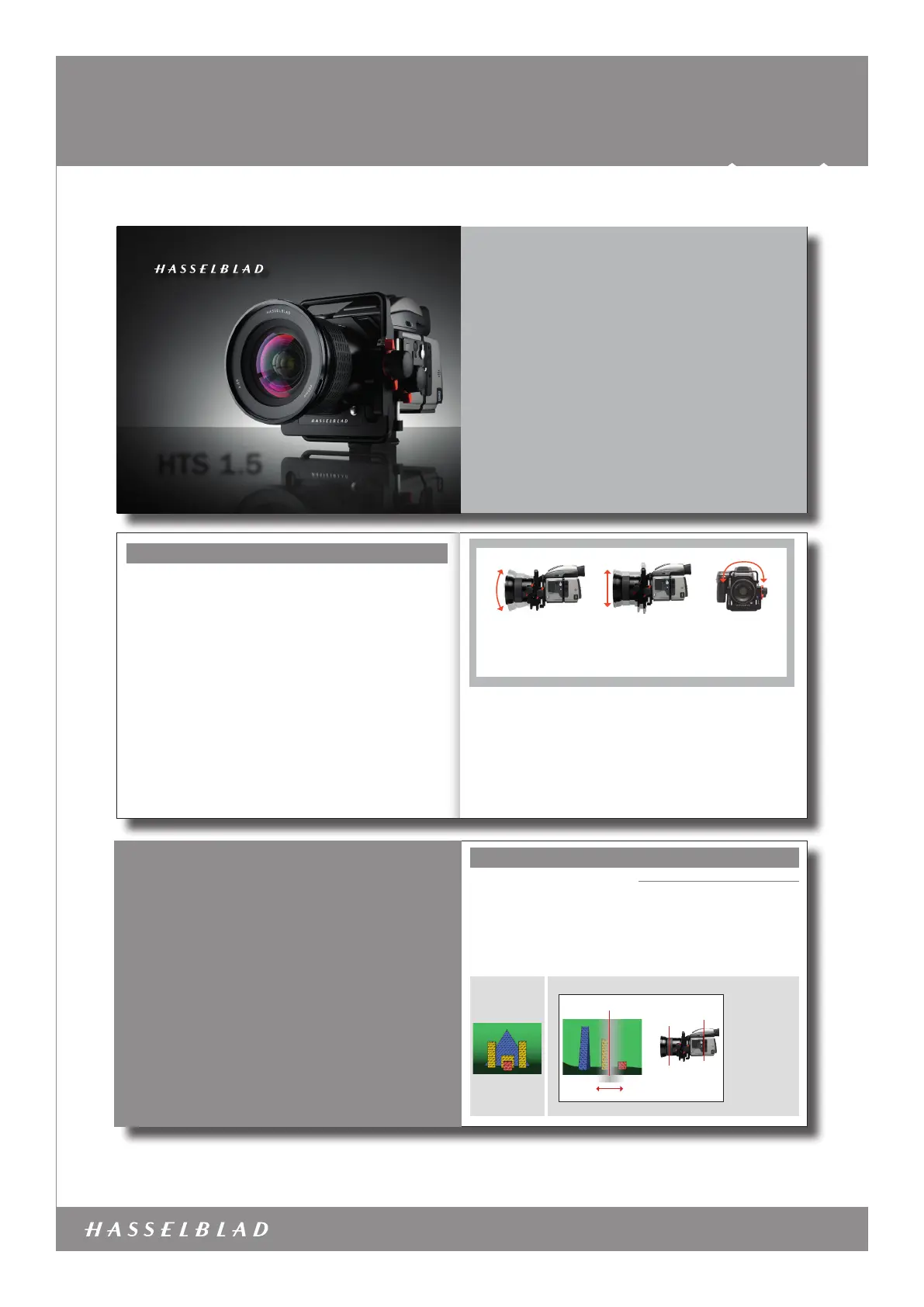
HTS 1.5 – 3043400 – 2011 – v3
Item no.: 3043400
HTS 1.5
1/8
4
HTS 1.5
HTS 1.5
5
Contents
Introduction1
Basic explanation of tilt 3
Basic explanation of shift 9
Getting started14
Tilt – in practice 19
Shift – in practice 23
Creative opportunities28
Appendix32
General points33
Scheimpug principle 34
Specications36
FAQ39
Terminology40
1
What is it ?
The HTS 1.5 is an accessory for H-system cameras that greatly
expands their usability both technically and creatively. It works
by allowing a lens to be moved in two different ways to meet
some challenges typically found in professional photography. It
is compact, simple to use and can prove to be an invaluable aid
in certain situations.
The HTS 1.5 adapter is mounted between the lens and the cam-
era body and, by way of the databus connections, automatically
conveys data to ensure the optimum in convenience and accu-
racy of exposure. This information is nally stored as metadata
with each le that can then be accessed in Phocus.
And it is in Phocus that DAC corrections automatically take into
account all tilt, shift and rotational movements as well as a
long list of specic lens data. This ability, unique to Hasselblad,
ensures the exceptional quality produced by the HTS 1.5.
What does it do?
The HTS 1.5 primarily solves problems but equally well pro-
motes creative opportunities to provide the photographer with
an almost invaluable tool.
Problem solving would be most obviously benecial in architec-
tural work, close-up product photography and certain kinds of
documentation, for example.
Creative opportunities would cover almost any area of photog-
raphy where a fresher approach is required regarding selective
focus and/or perspective manipulation.
How does it work?
It exploits established optical principles familiar to view camera us-
ers, namely ‘tilt’ and ‘shift’. These capabilities are further exploit-
ed by being able to rotate the whole unit. Only basic explanations
are included here as In-depth technical descriptions are beyond
the scope of this manual. A search on the Internet under headings
such as ‘camera movements’ and ‘Scheimpug Principle’, for
example, can provide much more insight into the concepts.
To be able to allow such movements using a lens from the stan-
dard range, an optical converter that increases lens coverage is
integrated into the design. In this way the adapter expands the
use of a number of lenses that many users already have thereby
avoiding the need for dedicated lenses.
Very simply put, tilting the lens moves the orientation of the
plane of sharp focus while shifting the lens moves the projected
image circle inside the camera.
What problems does it solve?
There are basically two areas that can be helped by tilt and
shift:
· Tilt is used when you want to change the orientation of the
plane of sharp focus.
· Shift is used to change the area selected for coverage of a
scene while retaining parallel lines in the image. It can also
used to create panoramas when used horizontally.
Although tilt is typically used in close-up product or landscape
photography and shift is typically used in architectural applica-
tions, it would be wrong to highlight these areas too much.
There are many situations where some tilt or some shift or
both would go a long way in producing a competitive edge on an
otherwise normal shot.
How is it creative?
The actions that produce practical solutions to problems create
effects that can also be classied as creative, dependent on
the intention. For example, it might be said that “stitching” (the
digital combining of several images) creatively exploits the ‘cor-
rect’ use of movements while selective de-focusing creatively
exploits the ‘incorrect’ use.
Hasselblad HTS 1.5 – Introduction
2
Compatibility
The HTS 1.5 was specically designed for use with the HCD
4/28mm and HC 2.8/80mm lenses, and these should be seen
as the primary choice for maximum performance. However, the
HC 3.5/35mm, HC 3.5/50mm and HC 2.2/100mm lenses can
also be used with excellent results. The 13mm, 26mm and
52 mm extension tubes are also compatible with all of these
lenses. The HC 3.2/150, HC 4/210 and HC 4.5/300 can also
be used but handling and performance are compromised and
are therefore not recommended for critical work.
Please note that the HTS 1.5 is not compatible with the
H1.7x converter, CF lens adapter, HC 3.5-4/50-110mm, HCD
4-5.6/35-90mm, or the HC 4/120mm Macro.
The autofocus and focus conrmation features on the camera
are also automatically de-activated for all lenses.
Tilt
Tilt changes the orientation of the
plane of sharp focus. This creates
the appearance of an ‘increase’ or
‘decrease’ in depth of field.
Shift
Shift allows perspective control
by preserving parallel lines in the
image. It also allows ‘stitched’
panoramas.
www.hasselblad.com
TILT AND SHIFT ADAPTER
MOVEMENTS - ROTATION
The HTS 1.5 adapter can be rotated 90 degrees
to the left or right to enable free placement of
sharpness plane and shift direction.
The integral converter in the HTS 1.5 alters the angle of view
(in effect, extending the focal length) of each lens and causes
some loss of speed. For example, a HC 2.8/80mm - HTS 1.5
combination will produce an image you might expect from a
4.5/128 mm lens on its own, as a rough guide. Please see
under Specications for full details.
For the HTS to function correctly, the rmware in the camera and Phocus soft-
ware must be recent. Please ensure you have the latest versions installed. You
can download them free of charge from:
http://www.hasselblad.com/service--support/technical-support/software-downloads
Rotation
Allows the whole unit,
at any tilt and shift set-
tings, to be rotated for
further control.
20º
total
180º
total
36mm
total
3
TILT
– a basic explanation
A classic problem in close-up product
photography and similar areas, is the lack
of depth of eld.
Using tilt can solve many such problems
as well as offering creative solutions.
4
With a basic understanding of the principles behind
tilt and shift, you will gain more confident control of
the HTS 1.5 and be able to exploit its potential to the
optimum.
The function of a camera lens is to project an image onto a sen-
sor. The sensor, being effectively two dimensional and lying in a
specic plane, can only record a two dimensional at plane, in
the same orientation, in the subject.
In practice we normally perceive some areas in front and behind
this at plane in the subject as “sharp” and this is termed the
depth of eld (which in its turn expands or contracts according
to aperture setting and subject distance).
Tilt
The lens is normally set perpendicular to the image plane and
therefore is effectively in parallel with the sensor as well. This
provides three planes to consider – the sensor, the lens and the
subject – all parallel. They are also interrelated, so moving one
will have an effect on the others. This is where tilt is introduced.
In the diagram below, the image plane, lens plane and subject
plane are parallel. This creates an area of acceptable sharp-
ness – the depth of eld. In this case, not all of the subject
lies within the boundaries of the depth of eld and those parts
therefore appear unsharp. By tilting the lens it is possible to
include more of the objects in the depth of eld without having
to use a smaller aperture.
Basic explanation of tilt
Tilt
Original scene
from camera
viewpoint
In this case, the lens is
focused in front of the
yellow object.
At the given aperture
setting, the yellow object
is covered by the depth
of field, the red object
partly covered and the
blue object not covered
at all. The yellow object
will therefore be accept-
ably sharp, the red object
partly sharp and the blue
object unsharp.
Lens plane
Image (sensor) plane
Depth of field
Subject plane
Termékspecifikációk
| Márka: | Hasselblad |
| Kategória: | nincs kategorizálva |
| Modell: | HTS 1.5 |
Szüksége van segítségre?
Ha segítségre van szüksége Hasselblad HTS 1.5, tegyen fel kérdést alább, és más felhasználók válaszolnak Önnek
Útmutatók nincs kategorizálva Hasselblad

29 Augusztus 2024
29 Augusztus 2024
Útmutatók nincs kategorizálva
Legújabb útmutatók nincs kategorizálva
10 Április 2025
10 Április 2025
10 Április 2025
9 Április 2025
9 Április 2025
9 Április 2025
9 Április 2025
9 Április 2025
9 Április 2025
9 Április 2025