Használati útmutató Klein Tools CL120KIT
Klein Tools
Mérőberendezések
CL120KIT
Olvassa el alább 📖 a magyar nyelvű használati útmutatót Klein Tools CL120KIT (25 oldal) a Mérőberendezések kategóriában. Ezt az útmutatót 14 ember találta hasznosnak és 7.5 felhasználó értékelte átlagosan 3.8 csillagra
Oldal 1/25
INSTRUCTION MANUAL
600V
400A
20M
Ω
FRANÇAIS pg. 33
ESPAÑOL pg. 17
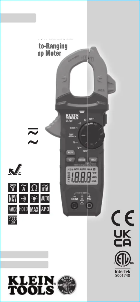
400A AC Auto-Ranging
Digital Clamp Meter
INSTRUCTION MANUAL
400A AC Auto-Ranging
Digital Clamp Meter
400A AC Auto-Ranging
Digital Clamp Meter
• NON-CONTACT
VOLTAGE TESTING
• AUTO-RANGING
• DATA HOLD
• RANGE HOLD
• AUDIBLE
CONTINUITY
ENGLISH
CL120KIT
2m
CAT III
600V
2 3
GENERAL SPECIFICATIONS
Klein Tools CL120 is an automatically ranging digital clamp-meter
that measures AC current via the clamp, and AC/DC voltage,
resistance and continuity via test-leads.
• Operating Altitude: 6562 ft. (2000 m)
• Relative Humidity: <95% non-condensing
• Operating Temp: 32° to 122°F (0° to 50°C)
• Storage Temp: 14° to 122°F (-10° to 50°C)
• Accuracy: Values stated at 65° to 83°F (18° to 28°C)
• Temp Coefcient: 0.1 x (Quoted Accuracy) per °C above
28°C or below 18°C, corrections are required when ambient
working temp is outside of Accuracy Temp range
• Dimensions: 8.46" x 3.54" x 1.50" (215 x 90 x 38 mm)
• Weight: 11.04 oz. (313 g) including batteries
• Calibration: Accurate for one year
• Auto Power-Off (APO): After approx. 10 minutes of inactivity
• Standards: IEC EN 61010-1, 61010-2-032, 61010-2-033.
IEC EN 61326-1, 61326-2-2.
Conforms to UL STD.61010-1,
61010-2-032,61010-2-033;
Certified to CSA STD.C22.2 NO. 61010-1,
61010-2-032,61010-2-033.
• Pollution degree: 2
• Accuracy: ± (% of reading + # of least significant digits)
• Drop Protection: 6.6 ft. (2m)
• Safety Rating: CATIII 600V, Class 2, Double insulation
• Electromagnetic Environment: IEC EN 61326-1. This
equipment meets requirements for use in basic and controlled
electromagnetic environments like residential properties,
business premises, and light-industrial locations.
Specifications subject to change.
ENGLISH
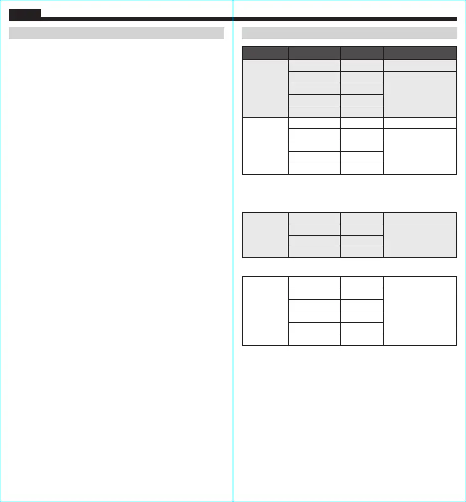
ELECTRICAL SPECIFICATIONS
Function Range Resolution Accuracy
AC Voltage
(V AC)
200.0mV 0.1mV ±(2.5% + 10 digits)
2.000V 1mV
±(2.0% + 5 digits)
20.00V 10mV
200.0V 100mV
600V 1V
DC Voltage
(V DC)
200.0mV 0.1mV ±(1.0% + 8 digits)
2.000V 1mV
±(1.0% + 3 digits)
20.00V 10mV
200.0V 100mV
600V 1V
Input Impedance: 10MΩ
Frequency Range: 45 to 400Hz
Maximum Input: 600V AC RMS or 600V DC
AC Current
(A AC)
2.000A 1mA ±(2.5% + 30 digits)
20.00A 10mA
±(2.0% + 10 digits)200.0A 100mA
400A 1A
Frequency Range: 50 to 60Hz
Resistance
200.0Ω 0.1Ω ±(1.2% + 5 digits)
2.000KΩ 1Ω
±(1.2% + 3 digits)
20.00kΩ 10Ω
200.0kΩ 100Ω
2.000MΩ 1kΩ
20.00MΩ 10kΩ ±(2.0% + 5 digits)
Maximum Input: 600V AC RMS or 600V DC
OTHER MEASUREMENT APPLICATIONS
Maximum Input: 600V DC or 600V AC RMS
• Continuity Check: Audible signal <10Ω, max current 1.5mA
• Sampling Frequency: Approx. 3 samples per second
• Overload: "OL" indicated on display
• Polarity: "-" on display indicates negative polarity
• Display: 3 ½ digit, 2000 Count LCD
4 5
ENGLISH
WARNINGS - GENERAL
To ensure safe operation and service of the meter, follow these instructions.
Failure to observe these warnings can result in severe injury or death.
• Before each use verify meter operation by measuring a known voltage
or current.
• Never use the meter on a circuit with voltages that exceed the category
based rating of this meter.
• Do not use the meter during electrical storms or in wet weather.
• Do not use the meter or test leads if they appear to be damaged.
• Use only with CAT III or CAT IV rated test leads.
• Ensure meter leads are fully seated, and keep fingers away from the
metal probe contacts when making measurements.
• Do not open the meter to replace batteries while the probes are connected.
• Use caution when working with voltages above 25V AC RMS or 60V DC.
Such voltages pose a shock hazard.
• To avoid false readings that can lead to electrical shock, replace batteries
when a low battery indicator appears.
• Do not attempt to measure resistance or continuity on a live circuit.
• Always adhere to local and national safety codes. Use personal protective
equipment to prevent shock and arc blast injury where hazardous live
conductors are exposed.
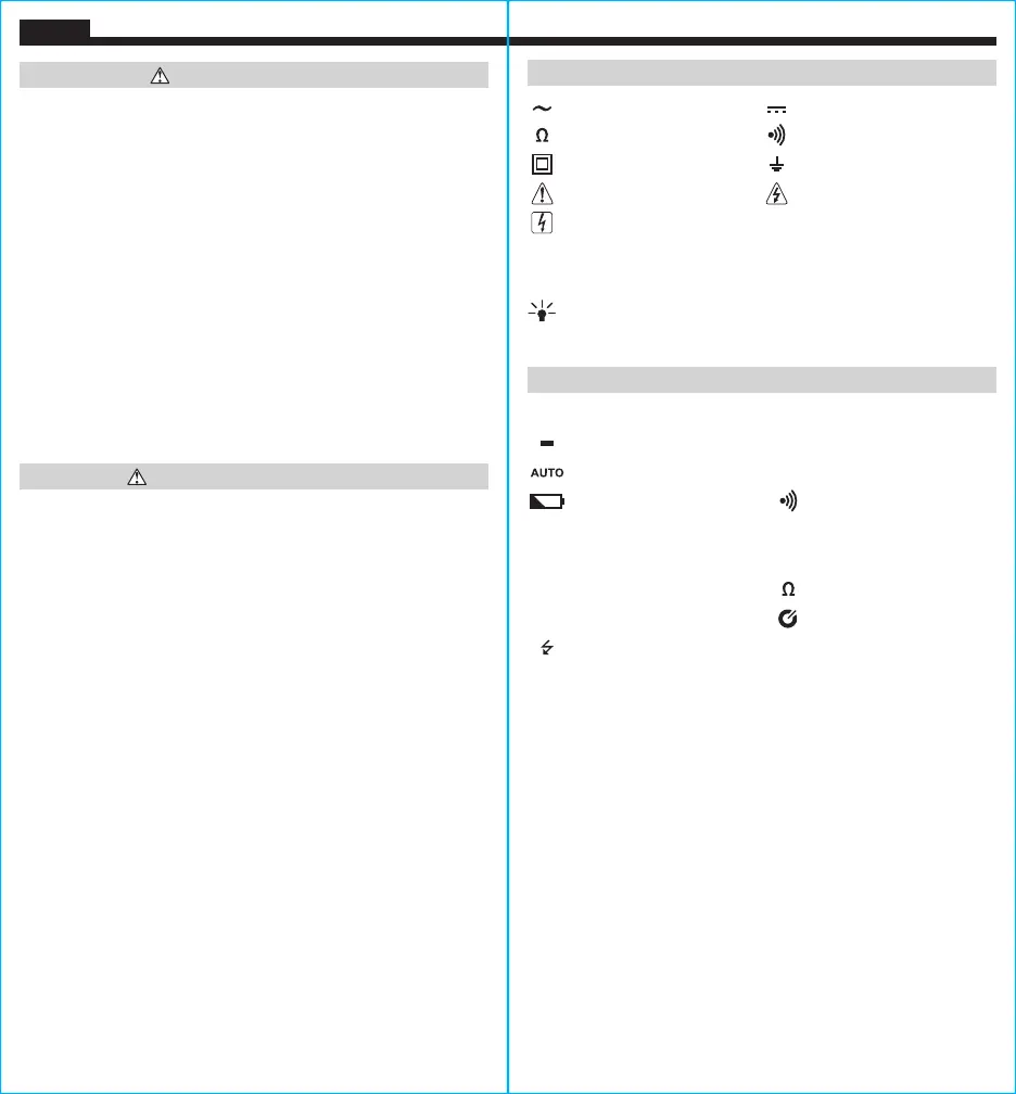
SYMBOLS ON METER
AC (Alternating Current) DC (Direct Current)
Resistance (in Ohms) Audible Continuity
Double Insulated Class II Ground
Warning or Caution
Risk of Electrical Shock
Suitable for uninsulated hazardous live conductors
V Voltage (Volts) A Amperage (Amps)
COM Common NCV Non-Contact Voltage Tester
Backlight SEL Select
+
Positive
–
Negative
SYMBOLS ON LCD
AC AC (Alternating Current) DC DC (Direct Current)
Negative Reading
H
Data Hold
Auto Ranging MAX Maximum Value Hold
Low Battery Audible Continuity
M
Mega (value x 10
6
)
k
kilo (value x 10
3
)
m
milli (value x 10
-3
)
V
Volts
A
Amps Ohms
NCV
Non-Contact Voltage Tester Auto Power-Off
Hazardous Voltage Indicator
WARNINGS - NCV FUNCTION
• When NCV Function is initiated, a blinking or steady red glow and an audible
beep indicate voltage present. If no indication, voltage could still be present.
• Before and after each use of the NCVT, verify operation by testing a known
working circuit that is within the rating of this unit.
• Never assume neutral or ground wires are de-energized. Neutrals in multi-wire
branch circuits may be energized when disconnected and must be retested
before handling.
• The NCV tester WILL NOT detect voltage if:
• The wire is shielded.
• The
operator is not grounded or is otherwise isolated from an effective earth ground.
• The voltage is DC.
• The NCV tester MAY NOT detect voltage if:
• The user is not holding the tester.
• The user is insulated from the tester with a glove or other materials.
• The wire is partially buried or in a grounded metal conduit.
• The tester is at a distance from the voltage source.
• The field created by the voltage source is blocked, dampened, or otherwise
interfered with.
• The frequency of the voltage is not a perfect sine wave between 50 and 500Hz.
• The tester is outside of operation conditions (listed in Specifications section).
• Operation may be affected by differences in socket design and insulation
thickness and type; tester may not be compatible with some types of standard
or tamper resistant (TR) electrical outlets.
• Do not apply to uninsulated hazardous live conductors.
• Detection above 50V is specified under “normal” conditions as specified below.
The tester may detect at a different threshold at different conditions, or may not
detect at all unless:
• The
tip of the tester is within 0.25" of an AC voltage source radiating unimpeded.
• The user is holding the body of the tester with his or her bare hand.
• The user is standing on or connected to earth ground.
• The air humidity is nominal (50% relative humidity).
• The tester is held still.
Termékspecifikációk
| Márka: | Klein Tools |
| Kategória: | Mérőberendezések |
| Modell: | CL120KIT |
Szüksége van segítségre?
Ha segítségre van szüksége Klein Tools CL120KIT, tegyen fel kérdést alább, és más felhasználók válaszolnak Önnek
Útmutatók Mérőberendezések Klein Tools

14 Január 2025

14 Január 2025

2 Január 2025

29 December 2024

24 Szeptember 2024

21 Szeptember 2024

21 Szeptember 2024

1 Szeptember 2024

1 Szeptember 2024

1 Szeptember 2024
Útmutatók Mérőberendezések
- Mérőberendezések Soler & Palau
- Mérőberendezések AkYtec
- Mérőberendezések Toolland
- Mérőberendezések Circutor
- Mérőberendezések Brookhuis
- Mérőberendezések Danfoss
- Mérőberendezések Hikmicro
- Mérőberendezések Be Cool
- Mérőberendezések Reely
- Mérőberendezések ClimeMET
- Mérőberendezések Intact
- Mérőberendezések Vimar
- Mérőberendezések Eastron
- Mérőberendezések Goobay
- Mérőberendezések Albrecht
Legújabb útmutatók Mérőberendezések

3 Április 2025

3 Április 2025

3 Április 2025

3 Április 2025

3 Április 2025

3 Április 2025

3 Április 2025

3 Április 2025

3 Április 2025

3 Április 2025