Használati útmutató Pelco RC-LED
Pelco nincs kategorizálva RC-LED
Olvassa el alább 📖 a magyar nyelvű használati útmutatót Pelco RC-LED (13 oldal) a nincs kategorizálva kategóriában. Ezt az útmutatót 30 ember találta hasznosnak és 2 felhasználó értékelte átlagosan 4.6 csillagra
Oldal 1/13
RC-LED INSTRUCTION MANUAL
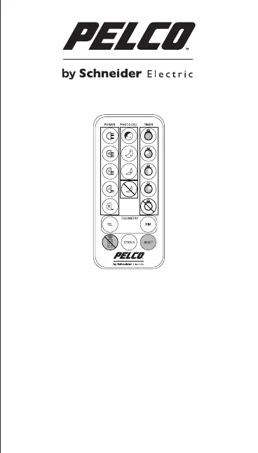
Control features
1. LED Status Feedback
System, Using the Remote
and Operating Modes
2. Power Adjust
3. Photocell Sensitivity
4. Wiring of Remote Switch
or Input (Telemetry Input)
4a.Telemetry – TEL –
Remote Switching
4b. Telemetry – DIM –
Remote Dimming
4c. Timer Function
5. LED Status Feedback
System
6. Restore Factory Default
Settings & Stored Memory
7. Disable Remote Control
Set-up
8. Control Feature
Combinations
9. Mechanical Details and
Battery Information
10. RC-LED Troubleshoot
1. LED Status Feedback System, Using
the Remote and Operating Modes
There are three, coloured LEDs visible on the base of the PELCO
illuminator. The three LEDs provide important operating and
status information. The infra-red receiver for the Remote Control
commands is also on the base of the unit – and the Remote
Control should be pointed in this direction during programming.
Most functions respond immediately to pressing the required
button – however two functions require the button to be held
for 4 seconds continuously to avoid accidental programming:
1.Restore Factory Default and 2.Disable Remote Control Set-up.
The Remote Control is designed to operate at distances up to
8 metres.
The status information provided by each of these LEDs differs
depending on which of the two operating modes the PELCO
illuminator is in: (A) Programming OR (B) Normal Operating.
1A. Programming Mode
On powering up the illuminator, it automatically enters
programming mode to allow the user to adjust set-up and
operation. The programming mode automatically times out
after 4 weeks or until the user actively disables the programming
mode - see ‘Disable Remote Control Set-up’ (section 7).
During Programming mode, the LEDs indicate the following
status:
• SOLID GREEN: Power Applied
• FLASHING GREEN: Remote control IR receiver problem
• FLASHING AMBER: Indicates unit is in programming
mode
• SOLID AMBER: Indicates that a valid command
is being received
• SOLID RED: Internal LED Fault Detected
• FLASHING RED: Voltage supply problem detected
*(Please note – once the voltage problem has been corrected, the
user must disable remote control set-up or power the unit on and off
to stop the red status LED flashing)
All functions of the Remote Control are available in
Programming Mode.
1B. Normal Operating Mode
During Normal Operating Mode (i.e. not in Programming
Mode), the LEDs indicate the following status:
• SOLID GREEN: Power Applied
• FLASHING GREEN: Remote control IR receiver problem
• SOLID AMBER: Voltage supply problem detected
**(Please note – once the voltage problem has been corrected, the
user must disable remote control set-up or power the unit on and off
to extinguish the amber status LED)
• SOLID RED: Internal LED Fault Detected
The only function of the Remote Control available during
Normal Operating Mode is LED Status Indicators Enable/
Disable (see section 5).
Factory Default: On initial power-up, illuminator
automatically defaults into programming mode.
Programming mode automatically disabled after 4 weeks.
2. Power Adjust
The power output of the PELCO illuminator can be adjusted
between 5 pre-set levels. To select the required light intensity
use the buttons shown. Factory default = 100% power.
80% of maximum
60% of maximum
40% of maximum
20% of maximum
100% of maximum
3. Photocell Sensitivity
There are three pre-defined levels to set the lux level threshold
at which the photocell turns the PELCO illuminator on/off.
To select the required sensitivity level use the buttons below.
Factory default = Medium Sensitivty:
10 Lux On, 30 Lux Off
IMPORTANT NOTE:
When the photocell disable button is selected this means
that the illuminator will turn on/off from a telemetry input,
regardless of ambient lighting conditions.
25 Lux On, 50 Lux Off
10 Lux On, 30 Lux Off
5 Lux On, 15 Lux Off
Photocell disabled
RC-LED - Quick Set Up Instructions
1. At power up, the unit enters programming mode
(FLASHING AMBER LED)
SOLID GREEN LED shows unit receiving power
FLASHING GREEN - Remote control IR receiver problem
SOLID AMBER LED shows unit receiving valid command
SOLID RED – Internal LED Fault Detected
FLASHING RED – Voltage supply problem detected
Unit stays in programming mode for 4 weeks or until remote
control set-up disabled
2. If required: Adjust Power
Press 5 for 100% power, 4 for 80%, 3 for 60%, 4 for 40% and
2 for 20% power. Factory Default = 100%
3. If required: Adjust Photocell Sensitivity
Press: Top Button for Low Sensitivity: 25 Lux On 50 Lux Off
2nd Button for Medium Sensitivity: 10 Lux On 30 Lux Off
3rd Button for High Sensitivity: 5 Lux On 15 Lux Off
Bottom button to disable photocell
Factory Default = Medium Sensitivity
Unit factory-set to turn on/off automatically from
Photocell. Orange and Purple Telemetry input wires are
joined to mimic volt-free input (dry contact). Separate
the wires to use with remote switch or input.
4. Telemetry Input - General Wiring of Remote Switch or Input
Any external switch or input must be wired into Orange and
Purple wires (Telemetry Input Wires). These wires accept
both volt-free input or TTL:
Volt-freeinput:Non Polarity Sensitive. Short circuit = Light On
TTL input: Orange = TTL+ve, Purple = TTL –ve (GND)
0V = Light On, 3V = Light Off
4a. TEL Select this option to turn lamp on/off remotely
from a remote input or switch. This is the factory
default setting.
4b. DIM Select DIM to dim lamp remotely from an input
or switch. First input reduces power. Second
input increases power … and so on.
4c.TIMER Press and release TEL – then select required
period of time for unit to stay on after Telemetry
Input. Timings associated with each button
shown in section 4 of main instructions.
To cancel Timer function press Timer Disable.
5. To turn LED Status Indicators on and off – Press STATUS
button.
6. To restore all factory settings press RESET button.
Defaults shown in section 6. This button must be pressed
continuously for 4 seconds to activate function.
7. Press this button to disable programming mode.
Button must be depressed for at least 4 seconds.
Only do this when you are happy with the set-up
and installation of your unit.
3500 Pelco Way Clovis, California 93612-5699 United States
USA & Canada Tel (800) 289-9100 Fax (800) 289-9150
International Tel +1 (559) 292-1981 Fax +1 (559) 348-1120
www.pelco.comwww.pelco.com/community
C3935M (9/13)
3500 Pelco Way, Clovis, California 93612-5999
Americas Tel: (800) 289-9100 International: (559) 292-1981
sales@pelco.com www.pelco.com
C3935M
Termékspecifikációk
| Márka: | Pelco |
| Kategória: | nincs kategorizálva |
| Modell: | RC-LED |
Szüksége van segítségre?
Ha segítségre van szüksége Pelco RC-LED, tegyen fel kérdést alább, és más felhasználók válaszolnak Önnek
Útmutatók nincs kategorizálva Pelco

11 December 2024
3 Szeptember 2024
19 Augusztus 2024
18 Augusztus 2024
16 Augusztus 2024
16 Augusztus 2024
15 Augusztus 2024
14 Augusztus 2024
Útmutatók nincs kategorizálva
Legújabb útmutatók nincs kategorizálva
10 Április 2025
10 Április 2025
10 Április 2025
9 Április 2025
9 Április 2025
9 Április 2025
9 Április 2025
9 Április 2025
9 Április 2025
9 Április 2025