Használati útmutató Audiovox PRO-PDL-25
Audiovox távirányító PRO-PDL-25
Olvassa el alább 📖 a magyar nyelvű használati útmutatót Audiovox PRO-PDL-25 (6 oldal) a távirányító kategóriában. Ezt az útmutatót 32 ember találta hasznosnak és 2 felhasználó értékelte átlagosan 4.4 csillagra
Oldal 1/6
PRO-PDL-25
2-DOOR
&
~AUDIOTOX~
PRO-PDL-45 4-DOOR
CORPORATION
POWER DOOR LOCK KIT
Installation
Instructions
PREPARING
FOR INSTALLATION
1. Review the
installation
drawings and wiring diagram to familiarize yourself
with the use and wiring
of
the system.
NOTE:
These instructions
apply
to both the 2
&
4-Door systems.
If installing the 2-Door system, ignore the section
applicable to the 4-Door system.
2. Determine where the
CONTROL
MODULE
will
be mounted. This
will normally
be behind the dash near the fuse
block
to
allow
for connection
of
the 12
Volt
Positive and Ground Wires.
3.
Examine the
WIRING HARNESS. You
will
find two groups
of
5 wires each (on 4-door
models
and two groups
of
2 wires
each).
One
of
the 5-wire harnesses
will
be shorter than the other. This short harness is to be routed to the front door nearest
the mounting
location
ofthe
CONTROL
MODULE.
4. Remove the door panels
on
all
doors.
CONTROL MODULE MOUNTING
&
WIRE ROUTING
1. Select
a mounting
location for the
CONTROL
MODULE and secure it with 5
x 16 mm screw.
2.
Plug
the wiring harness into the
control module.
3.
Route the
SHORT
5-wire harness to the FRONT door nearest the
CONTROL
MODULE by the
following
method:
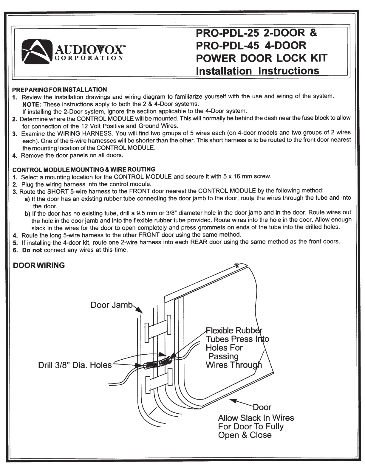
a)
If
the door has an existing rubber tube connecting the door jamb to the door, route the wires through the tube and into
th~
door.
b)
If the door has no existing tube,
drill
a 9.5 mm
or
3/8"
diameter
hole
in the door jamb and in the door. Route wires out
the
hole in the door jamb and into the flexible rubber
tube provided. Route wires into the
hole
in the door.
Allow
enough
slack in the wires for the door to open
completely
and press grommets on ends
of
the tube into the
drilled holes.
4. Route the long
5-wire harness to the other FRONT door using the same method.
5.
If installing the 4-door kit, route one 2-wire harness into each REAR door using the same method as the front doors.
6.
Do
not
connect any wires at this time.
DOOR WIRING
Door
Jamb"
lexible Rubb
Tubes Press
I
Holes For
Passing
Wires Throu
Allow Slack
In
Wires
For Door
To
Fully
Open
&
Close
Termékspecifikációk
| Márka: | Audiovox |
| Kategória: | távirányító |
| Modell: | PRO-PDL-25 |
Szüksége van segítségre?
Ha segítségre van szüksége Audiovox PRO-PDL-25, tegyen fel kérdést alább, és más felhasználók válaszolnak Önnek
Útmutatók távirányító Audiovox

27 Augusztus 2024
27 Augusztus 2024
27 Augusztus 2024
27 Augusztus 2024
27 Augusztus 2024
27 Augusztus 2024
27 Augusztus 2024
27 Augusztus 2024
27 Augusztus 2024
27 Augusztus 2024
Útmutatók távirányító
Legújabb útmutatók távirányító
9 Április 2025
3 Április 2025
2 Április 2025
1 Április 2025
31 Március 2025
29 Március 2025
29 Március 2025
27 Március 2025
27 Március 2025
27 Március 2025