Használati útmutató Hinkley Lighting Axel 4513BK
Hinkley Lighting
Megkönnyebbülés
Axel 4513BK
Olvassa el alább 📖 a magyar nyelvű használati útmutatót Hinkley Lighting Axel 4513BK (3 oldal) a Megkönnyebbülés kategóriában. Ezt az útmutatót 14 ember találta hasznosnak és 7.5 felhasználó értékelte átlagosan 4.9 csillagra
Oldal 1/3

H I N K L E Y L I G H T I N G 33000 Pin Oa k P arkway, Avon Lake, OH 44 0 1 2 800.446.5539 / 4 40.653.5500 h i n k leylighting.com
Assembly Instructions
Item No. 4513
Les Instructions D’assemblage
Numéro d’article: 4513
Instrucciones De Montaje
Número del artículo: 4513
start here commencez ici
empezar aquí
1. Find a clear area in which you can work.
8QSDFN¿[WXUHDQGJODVVIURPFDUWRQ
&DUHIXOO\UHYLHZLQVWUXFWLRQVSULRUWRDVVHPEO\
(QFRQWUDUXQiUHDFODUDHQODTXHVHSXHGHWUDEDMD
'HVHPEDOHOXPLQDULD\HOYLGULRGHODFDMD
5HYLVHFXLGDGRVDPHQWHODVLQVWUXFFLRQHVDQWHVGHOPRQWDMH
URXYH]XQHQGURLWFODLUGDQVOHTXHOYRXVSRXYH]WUDYDLOOH
'pEDOOH]OXPLQDLUHHWGHYHUUHGXFDUWRQ
([DPLQH]DWWHQWLYHPHQWOHVLQVWUXFWLRQVDYDQWODVVHPEODJH
1. T
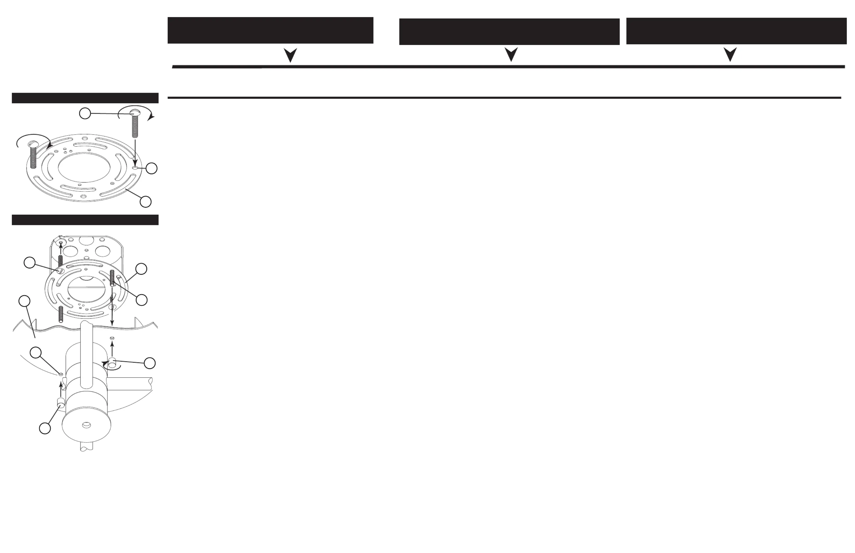
DRAWING 2 - MOUNTING
1. TREHJLQLQVWDOODWLRQLWZLOOILUVWEHQHFHVVDU\WRPRXQWWKHPDLQ
ERG\WRWKHMXQFWLRQER[ 7KLVLVDFFRPSOLVKHGE\ILUVWSUHSDULQJ
WKHPRXQWLQJVWUDS$IRULQVWDOODWLRQVHH'UDZLQJ
2. TDNHPRXQWLQJVWUDS$DQGORFDWHWKHWZRWKHDGHGKROHV7LQ
WKHSODWHWKDWDUHWKHVDPHGLVWDQFHDSDUWDVWKHWZRKROHV(
LQWKHFDQRS\'VHH'UDZLQJ
1RZWDNHRQHRIWKHORQJPRXQWLQJVFUHZV%SURYLGHGDQG
WKUHDGLWLQWRKROH7IURPWKHEDFNRIWKHPRXQWLQJVWUDS
NOTE: 7KHIURQWRIWKHPRXQWLQJVWUDSKDVWKHKHDGRIWKH
JURXQGVFUHZVKRZLQJ
7KUHDGWKHVFUHZVGRZQXQWLOWKHKHDGRIWKHVFUHZLV
DSSUR[LPDWHO\´DERYHWKHPRXQWLQJVWUDS $IWHUERWKVFUHZV
DUHLQSODFHFKHFNWRVHHLIWKHVFUHZVZLOOSDVVWKURXJKKROHV
(LQWKHFDQRS\'
0RXQWLQJVWUDS$FDQQRZEHDWWDFKHGWRMXQFWLRQER[-8VH
WZRVFUHZV&´ORQJ12 3529,'('RUXVHWKHT
VFUHZVIURPWKHSUHYLRXVLQVWDOODWLRQVHH'5AWING 2.
5. 7KHERG\RIWKHIL[WXUHFDQQRZEHPRXQWHGWRWKH-XQFWLRQ
ER[ 7KLVLVDFFRPSOLVKHGE\ILUVWPDNLQJDOOZLULQJFRQQHFWLRQV
IROORZLQJLQVWUXFWLRQVKHHW,6SURYLGHG
$VVLVWDQFHP\EHUHTXLUHGGXULQJWKLVRSHUDWLRQ
6. $IWHUZLULQJLVFRPSOHWHWXFNZLUHVLQWRMXQFWLRQER[DQGOLIW
IL[WXUHXSWRFHLOLQJDQGDOLJQKROHV(LQFDQRS\ZLWKVFUHZV
%LQPRXQWLQJSODWH6OLSVFUHZVWKURXJKKROHVDQGVOLS
FDQRS\XSDJDLQVWWKHFHLOLQJDQGKROGLQSRVLWLRQ
1RZWDNHEDUUHONQREV)DQGWKUHDGWKHPRQWRWKHHQGRI
VFUHZV%DQGWLJKWHQXQWLOFDQRS\LVWLJKWDJDLQVWWKHFHLOLQJ
HFDQQRZSURFHHGWRLQVWUXFWLRQVKHHWWRFRQWLQXHW
LQVWDOODWLRQ
DRAWING 1 - MOUNTING
B
C
D
E
F
A
T
A
B
F
3DUDFRPHQ]DUODLQVWDODFLyQSULPHURVHUiQHFHVDULR
PRQWDUHOFXHUSRSULQFLSDOHQODFDMDGHFRQH[LRQHV(VWR
VHORJUDSUHSDUDQGRSULPHURODFRUUHDGHPRQWDMH$
SDUDODLQVWDODFLyQFRQVXOWHHO'LEXMR
2. TRPHODFRUUHDGHPRQWDMH$\XELTXHORVGRVRULILFLRV
FRQFDEH]D7HQODSODFDTXHHVWiQVHSDUDGRVDOD
PLVPDGLVWDQFLDTXHORVGRVRULILFLRV(HQODFXELHUWD
'YHDHO'LEXMR
3. $KRUDWRPHXQRGHORVWRUQLOORVGHPRQWDMHODUJRV%
SURYLVWRV\HQUyVTXHORHQHORULILFLR7GHVGHODSDUWH
SRVWHULRUGHODFRUUHDGHPRQWDMH12T$/DSDUWHIURQWDO
GHODFRUUHDGHPRQWDMHPXHVWUDODFDEH]DGHOWRUQLOORGH
WLHUUD
(QURVTXHORVWRUQLOORVKDFLDDEDMRKDVWDTXHODFDEH]D
GHOWRUQLOORTXHGH
DSUR[LPDGDPHQWHPPSRUHQFLPDGHODFRUUHDGH
PRQWDMH'HVSXpVGHTXHDPERVWRUQLOORVHVWpQHQVX
OXJDrYHULILTXHVLORVWRUQLOORVSDVDUiQDWUDYpVGHORV
DJXMHURV(HQODFXELHUWD'
/DFRUUHDGHPRQWDMH$DKRUDVHSXHGHXQLUDODFDMD
GHFRQH[LRQHV-8VHGRVWRUQLOORV&GHODUJR
12680,1,675$'26RXVHORVWRUQLOORVGHOD
LQVWDODFLyQDQWHULRUYHD',%8-2
(OFXHUSRGHOGLVSRVLWLYRDKRUDVHSXHGHPRQWDUHQOD
FDMDGHFRQH[LRQHV(VWRVHORJUDKDFLHQGRSULPHUR
WRGDVODVFRQH[LRQHVGHFDEOHDGRKRMDGHLQVWUXFFLRQHV
,6SURSRUFLRQDGDV6HSXHGHUHTXHULUDVLVWHQFLD
GXUDQWHHVWDRSHUDFLyQ
'HVSXpVGHFRPSOHWDUHOFDEOHDGRPHWDORVFDEOHVHQOD
FDMDGHFRQH[LRQHV\OHYDQWHHODFFHVRULRKDVWDHOWHFKR
\DOLQHHORVDJXMHURV(HQODFXELHUWDFRQORVWRUQLOORV
%HQODSODFDGHPRQWDMH'HVOLFHORVWRUQLOORVDWUDYpV
GHORVDJXMHURV\GHVOLFHODFXELHUWDFRQWUDHOWHFKR\
PDQWpQJDODHQSRVLFLyQ
7. $KRUDWRPHODVSHULOODVGHOFDxyQ)\HQUyVTXHODVHQHO
H[WUHPRGHORVWRUQLOORV%\DSULHWHKDVWDTXHOD
FXELHUWDTXHGHDSUHWDGDFRQWUDHOWHFKR
$KRUDSRGHPRVFRQWLQXDUFRQODKRMDGHLQVWUXFFLRQHV
SDUDFRQWLQXDULQVWDODFLyQ
3RXUFRPPHQFHUO¶LQVWDOODWLRQLOIDXWG¶DERUGPRQWHUOH
FRUSVSULQFLSDOVXUODERvWHGHMRQFWLRQ&HFLHVWDFFRPSOL
HQSUpSDUDQWG¶DERUGODVDQJOHGHPRQWDJH$SRXU
O¶LQVWDOODWLRQYRLUGHVVLQ
3UHQH]ODVDQJOHGHPRQWDJH$HWORFDOLVH]OHVGHX[
WURXVILOHWpV7GHODSODTXHTXLVRQWjODPrPHGLVWDQFH
TXHOHVGHX[WURXV(GHODFRXSROH'YRLU'HVVLQ
0DLQWHQDQWSUHQH]OXQHGHVORQJXHVYLVGHIL[DWLRQ%
IRXUQLHVHWLQVpUH]ODGDQVOHWURX7VLWXpjODUULqUHGe la
EULGHGHIL[DWLRQ5(0$548(/DWrWHGHODYLVGHWHUUH
HVWYLVLEOHjODYDQWGHODVDQJOHGHPRQWDJHVLVVH]OHV
YLVMXVTXjFHTXHODWrWHGHODYLVVRLWHQYLURQPP
DXGHVVXVGHODVDQJOHGHPRQWDJH8QHIRLVOHVGHX[YLV
HQSODFHYpULILH]VLHOOHVSDVVHQWjWUDYHUVOHVWURXV(GH
ODFRXSROH'
/DVDQJOHGHPRQWDJH$SHXWPDLQWHQDQWrWUHIL[pHjOD
ERvWHGHMRQFWLRQ-8WLOLVH]GHX[YLV&GH00
GHORQJ121)2851,(6RXXWLOLVH]OHVYLVGH
O¶LQVWDOODWLRQSUpFpGHQWHYRLU6&+e0A 2.
/HFRUSVGHODSSDUHLOSHXWPDLQWHQDQWrWUHPRQWpVXUOD
ERvWHGHMRQFWLRQ3RXUFHIDLUHYRXVGHYH]GDERUG
eIIHFWXHUWRXWHVOHVFRQQH[LRQVGHFkEODJH
ILFKHGLQVWUXFWLRQ,6IRXUQLH/DVVLVWDQFHSHXWrWUH
QpFHVVDLUHSHQGDQWFHWWHRSpUDWLRQ
8QHIRLVOHFkEODJHWHUPLQpUHQWUH]OHVILOVGDQVODERvWH
GHMRQFWLRQHWVRXOHYH]OHOXPLQDLUHMXVTXDXSODIRQGHW
DOLJQH]OHVWURXV(GXSDYLOORQDYHFOHVYLV%GHOD
SODTXHGHPRQWDJH*OLVVH]OHVYLVGDQVOHVWURXVHW
SODFH]OHGDLVFRQWUHOHSODIRQGHWPDLQWHQH]OHHQSODFH
0DLQWHQDQWSUHQH]OHVERXWRQVGHFDQRQ)HWYLVVH]OHV
jOH[WUpPLWpGHVYLV%HWVHUUH]MXVTXjFHTXHOHGDLV
VRLWVHUUpFRQWUHOHSODIRQG
1RXVSRXYRQVPDLQWHQDQWSDVVHUjODILFKHGLQVWUXFWLRQV
SRXUFRQWLQXHULQVWDOODWLRQ
PAGE 1
H
I
N
K
L
E
Y

33 0 00 Pin Oak Parkw , on Lake, OH 4 4 012 800. 4 46.5539 / 4 40.653.5500 hinkley l ighting.cay Av om
Assembly Instructions
Item No. 4513
Les Instructions D’assemblage
Numéro d’article: 4513
Instrucciones De Montaje
Número del artículo: 4513
start here commencez ici
empezar aquí
PAGE 2
U
M
O
L
ANCHORS
ANCLA
ANCRE
SCREWS
EMPULGUERAS
LA VIS
SCREWS
EMPULGUERAS
LA VIS
1
3
4
2. Now take decorative washer (4) and place inside glass
(3) aligning the center hole of the washer with the center
hole of the glass. Next slip socket throught center hole of
glass and washer and hold in poisiton. Then thread on
socket cover (1) to secure glass. Repeat process for
remaing glass.
3. Fixture can now be lamped accordingly.
2. Ahora tome la arandela decorativa (4) y coloque el
vidrio interior (3) alineando el orificio central de la
arandela con el orificio central del vidrio. Luego deslice
el enchufe a través del orificio central del vidrio y la
arandela y sostenga el veneno. Luego, enrosque la
tapa del enchufe (1) para asegurar el vidrio. Repita el
proceso para el vidrio restante.
3. La luminaria ahora se puede laminar en
consecuencia.
2. Maintenant, prenez la rondelle décorative (4) et placez-la à
l'intérieur du verre (3) en alignant le trou central de la rondelle
avec le trou central du verre. Glissez ensuite la douille dans le
trou central du verre et de la rondelle et maintenez-la en place.
Puis vissez le couvercle de la douille (1) pour fixer le verre.
Répétez le processus pour le verre restant.
3. L'appareil peut maintenant être éclairé en conséquence.

H I N K L E Y L I G H T I N G 33000 Pin Oak Parkway Avon Lake, OH 44012 800.446.5539 / 440. 653.550 0 hinkleylighting.com
I.S. 18
wiring grounding instructions
SAFE TY WARNI NG: READ WIRIN G AND GROUNDING
INSTRUCTIO NS (IS 18) AND ANY A DDITIONAL DIRECTIONS.
TURN POWER SUPPLY OFF DURING INSTALLATION. IF NEW
WIRING IS REQUIRED, CONSULT A QUALIFIED ELECTRICIAN OR
LOCAL AUTHORITIES FOR CODE REQUIREMENTS
wiring instructions
Indoor Fixtures
1. Connec t po sitive supp ly wire (A ) (typical ly black or the smoo th,
unma rked side of the two-conduc tor cord) to positive fi xture lead (B )
with ap propriately sized t wist on connec tor - see Dra w ings 1 o r 2.
2. Connec t nega tive supply wi re (C
)
(typically whi te or the ribbed , marked
side of the two-conduc tor cord) to nega tive fixture lead (
D)
.
3. Ple ase refe r to the grou nding nst ructions i below to complet e all
electrical connec tion s
Outdoor Fixtures
1. Connec t po sitive supp ly wire (A ) (typically black or the smooth
unma rked side of the two-conduc tor cord) to positi ve fi xture lead (
B)
with ap propriately sized twist on connec tor --- see D
r
a
wi
ngs
2 o
r
3.
2. Connec t nega tive supply wi re (C) (t ypically white or the ribbed , marked
side of the two-conduc tor cord) to nega tive fixture lead (
D
).
3. Cove r open end of connec tors w ith sili cone sealant to fo rm a
watert ight seal.
If installi ng a wall moun t fixture, use caulk to seal gaps between the
fi xture mo unting p late (backpla te) and the w all. This will help prevent
wa ter fr om entering the out let box. If the wal l sur f ace is lap siding, use
caulk and a fi xture moun ting plat form specially.
4. Ple ase refe r to the grou nding nst ructions i below to complet e all
electrical connec tion s.
grounding instructions
Flush Mount Fixtur es
For po sitive ground ing in a 3-wir e elect ri cal system, f asten the fi xture
ground wir e (E) (typ ically coppe r or green plastic coated) to the fi xture
moun ting strap (M ) wit h the ground screw ( S) - see Draw in g 1 .
Note: On straps for screw supported fixtures, first install the two mounting
screws in strap. Any remaining tapped hole may be used for the ground screw.
Chain Hung Fixtur es
Loop fi xture ground wire (E ) (typically coppe r or green plast ic coa ted)
unde r the head of the ground screw ( S ) on fi xture mounting strap (M )
and connec t to the l oo se end of the fi xture ground wire directly to the
ground w ire of the bu ilding system with ap propri ately sized twist-on
connec tors - see Dr aw in g 2 .
Post-Mou nt Fixtur es
Connec t fixture ground wire (E ) (typically copper or green plastic coa ted)
to power supp ly ground wit h appr opria tely sized twist-on connec tor
inside post. Cove r open end of connec tor wi th silicone sealant to form a
wate rt ight seal - see Drawing 3.
I.S. 18
câblage échouage instructions
AVERTIS SEMEN T DE SECURITE: LIRE CABL AGE ET INSTRUCTI ONS DE
MISE (IS 18), ET TOUTE AUTRE INSTRUCTION. COUPER L’ALIMENT ATION
ELECTRI QUE PENDANT L’ONSTALLATI ON. SI DE NOUVELLES CABLAGE
N’EST NECESS AIRE, CONSULTEZ UN ELECTRICIE N QUALIFIE OU
AUTORITE S LOCALE S POUR EXI GENCES DU CODE.
instructions de câblage
Luminaires Itérieurs
1. Branche r le fi l d’al imentation po sit ive (A ) (généra lemen t noi r ou, côté lisse
bana lisée de l a corde á deux condu cteu rs) á plob de fi xation positi ve (
B) avec
la tor sion de taille app rop riée sur le connec teu r --- V
o
i
r
Schéma 1
o
u 2
.
2. Connec ter le fi l d’a limen tation néga tive (C) (génér alement blanc ou l’, côté
marqué nervu rée du fil á deux conducteurs) au conduc teur négat if de
l’a ppa reil (
D
).
3. S’il vou s plaît se réfé rer á la mise á la erre nstru ctions t i ci-des sou s pour
terminer tou tes les connex ions électriques .
Luminaires Ex t érieurs
1. Branche r le fi l d’al imen tation po sitive (
A) (généra lemen t noi r ou le côté lisse
bana lisée de la corde á deux condu cteu rs) á plomb de fi xat ion positi ve (
B)
avec la torsion a pprorpriately taille du connecteur --- V
oir Schéma u . 2 o 3
2. Connec ter le fi l d’a limen tation néga tive (C) (génér alement blanc ou l’, côté
marqué nervu rée du fi l á deux conduc teurs) au conduc teur négat if de
l’apparei ld (
D).
3. Couv rir extr émité ouve rt e de conn ecteur s acex du silicone pou r former un
joint étenche á l’ea u.
Si l’instal lation d’un lumina ire de montage mural, utiliser cal feut rage pou r
sceller l’espace entre la plaque de mon tage de fi xa tion (plaque arri ére) et la
paroi. Cela aidera á empêche r l’eau de péné trer dan s le boc sortie. Si la
surf ace du mur est ba rdage á clin, utiliser caldeutrage et un e plate-f orme de
mon tage d’appa reils spécialement .
4. S’i l vou s plait se re ferrer auc instruction s ci-des sous pou r terminer la ter re
toutes les c
onnexion s électrques .
instructions de mise
Montage Encastr é Fixtur es
Pour l a terre positive dan s un systéme électr ique á 3 fil s, fi xez le fil de terre du
luminaire (
E) (géné ralement en cuivre ou ver t recouver t de plastique) á la sangle
de fi xat ion de fi xation (
M ) S) avec la vis de te rre ( --- V oir Schém a . 1
Remarque: Sur les sangles pour les appareils pris en charge á vis, installez d’abord les
deux vis de fixation á sangle. Tout trou taraudé restante peut être utilisée pour la vis de
terre.
Chaîne Accroc hé Luminaires
Bouc le fil du lumina ire au sol (E ) (général ement en cuivre ou vert r ecouve rt de
plasti que) sous la tê te de la vis de terre (
S) sur la sangle de fi xa tion de fi xation
(
M ) et se connec ter á l’extr émitré libre du fi l de terre du luminaire directemen t
sur le fi l de t erre du systéme de con struction avec une taille app rop riée
connec teu rs á visser --- V
oir Schéma . 2
Luminaires Ap rés Mo ntage
Branche r le fi l de terre du luminair e (E)
(génér aleme nt en cuivr e ou vert
recouve rt de plastique) á la masse de l’alimentation avec une taille app ropriée
torsion sur le connec teur á l’intéri eur de la poste. Couvr ir ext rém ité ouver te du
connec teur avec du mast ic silicone pour f ormer un joint étache á l ’eau --- V
oir
S
ch
é
ma 3
.
I.S. 18
tierra cableado instrucciones
ADVER TENCI A DE SEGURIDAD : LEA LAS INSTRUCCIONES DE CABLEADO
Y LA TIERRA (IS 18), E INSTRUCCIONES ADICIONALES . APAUGE LA
ALIMENTACIÓN DE CORR IENTE DURANTE LA INSTALACIÓN. SI SE
REQU IERE NUEVO CABLEADO, CONSUL TE CON UN ELECTRICIST A O
AUTHORID ADES LOCALES PARA REQUISITO S DEL CÓDIGO
Instrucciones de cableado
Acesorios C ubierta
1. Conec te el cable de alimentación positi ve (A ) (no rmalmen te negro o la cara
lisa, sin mar cas del cable de dos conduc tores) de plomo accesorio positivo (
B)
con un giro de tamaño adecuado en el conec tor --- V
éase a igur a l F 1 y 2.
2. Conec te el cable de alimentación nega tiva (C) (po r lo gene ral de color
blanco o el lado mar cado estriado del cable de dos conduc tores) de plomo
acces orio negativo (
D).
3. Por favor, consult e las instruccione s de pues ta a tier ra-a continuac ión para
comp letar t odas las conex iones eléctricas.
Accesorios E x t erior
1. Conec te el cable de alimentación positi va (A ) (no rmalmen te negro el lado no
marcado suave del cable de dos condu ctores) de plomo accesorio positivo (
B)
con un giro de tamaño app rorpriately conector --- V
éase a igur a l F 2 y 3.
2. Conec te el cable de alimentación nega tive ( C) (po r lo gene ral de color
blanco o el lado mar cado estriado del cable de dos conduc tores) de plomo
acces orio negativo (
D).
3. Cubra el ext reme ab ierto de conecto res con sellador de silicona poa ra f ormar
un sello hermético.
Si va a i nstalar un sopo rte de fi jación mu r al, use masilla para sella los
espacios entre la placa de monta je del apa rato (placa) y la pared. Esto
ayuda rá a evitar que el agua entre en la boc salida. Si la supe rfi cie de l a
pared es de revestim iento solapado , utilice masilla y una plataforma de
montaje acce sorio especial .
4. Por fa vor, consulte las Ins
t
rucciones d
e
puest a ierra a t -a cont inuac ión pa ra
comp letar t odas las conex iones eléctricas.
instrucciones puesta a tierra
Montaje Embutido Accesorio s
Par a conect ar a ti erra en un sistem a elé ctrico de 3 hil os, fije el cable de tie rra
del artef a cto (
E) (generalme nte de cobre o verd e rec ubierto de plástico) a la
brida de montaje acce sorio (
M
)
con el tornillo de tie rra (
S
) --- V é
a
se a l
Figu
r
a
1.
Nota : En las correas de accesor ios compati bles tornill os, primero instale los dos
tornillos de mon taje de la correa. Cua lquier agu jero roscado restante puede ser
utilizado para el to r nillo de tierra.
Cadena Hung Accesorios
Loop alambre de tierra ( E) (gene ralmen te de cob re o verde recub ierto de
plát ico) deba jo de la cabeza del t ornillo de tierra (
S) en la brida de montaje
acces orio (
M )
y conectar con el ext remo suelto del cable de tierra luminar ia
directame nte al cab le de tier ra del sistema de constr ucción con un tamaño
adecu ado twist-conectores --- V
éase a igura . l F 2
Accesorios Post erior Mont e
Conec te el cable de tierr a del arte f acto (E) (gener almente de cobre o verde
recubierto de pl ástico) a tierr a de la fuente de alimentacón con conec tor de
tamanño adecua do en el interior puesto en laces en forma. Cub ra el extremo
abierto del conecto r con sellador de silicona para formar un sello he rmético ---
V
éase a l Figur a . 3
Drawin
g
1 – Flus h M ount
Drawin
g
2 – Chain Hun
g
Drawin
g
3 – Post-M ount
S
M
M
S
Termékspecifikációk
Márka: | Hinkley Lighting |
Kategória: | Megkönnyebbülés |
Modell: | Axel 4513BK |
Szüksége van segítségre?
Ha segítségre van szüksége Hinkley Lighting Axel 4513BK, tegyen fel kérdést alább, és más felhasználók válaszolnak Önnek
Útmutatók Megkönnyebbülés Hinkley Lighting
5 Január 2025
5 Január 2025
5 Január 2025
5 Január 2025
5 Január 2025
5 Január 2025
5 Január 2025
5 Január 2025
5 Január 2025
5 Január 2025
Útmutatók Megkönnyebbülés
- Megkönnyebbülés Merlin Gerin
- Megkönnyebbülés XQ-lite
- Megkönnyebbülés Showtec
- Megkönnyebbülés Kern
- Megkönnyebbülés GoGen
- Megkönnyebbülés Ring
- Megkönnyebbülés Schwaiger
- Megkönnyebbülés Reflecta
- Megkönnyebbülés Smith-Victor
- Megkönnyebbülés Cateye
- Megkönnyebbülés Adastra
- Megkönnyebbülés Anslut
- Megkönnyebbülés Stamos
- Megkönnyebbülés Briloner
- Megkönnyebbülés Toolcraft
Legújabb útmutatók Megkönnyebbülés
9 Április 2025
9 Április 2025
9 Április 2025
8 Április 2025
8 Április 2025
8 Április 2025
7 Április 2025
5 Április 2025
5 Április 2025
5 Április 2025