Használati útmutató Tru Components TX4S-14R
Tru Components Grillplaat TX4S-14R
Olvassa el alább 📖 a magyar nyelvű használati útmutatót Tru Components TX4S-14R (2 oldal) a Grillplaat kategóriában. Ezt az útmutatót 28 ember találta hasznosnak és 2 felhasználó értékelte átlagosan 4.7 csillagra
Oldal 1/2
Read and understand the instruction manual before using the product.
For your safety, read and follow the below safety considerations before using. For your safety,
read and follow the considerations written in the instruction manual.
Keep this instruction manual in a place where you can find easily.
The specifications, dimensions, etc are subject to change without notice for product improvement.
Safety Considerations
•Observe all ‘Safety Considerations’ for safe and proper operation to avoid hazards.
• symbol indicates caution due to special circumstances in which hazards may occur.
WarningFailure to follow instructions may result in serious injury or death
01. Fail-safe device must be installed when using the unit with machinery that may cause
serious injury or substantial economic loss.(e.g. nuclear power control, medical equipment,
ships, vehicles, railways, aircraft, combustion apparatus, safety equipment, crime/disaster
prevention devices, etc.)
Failure to follow this instruction may result in personal injury, economic loss or fire.
02. Do not use the unit in the place where flammable/explosive/corrosive gas, high humidity,
direct sunlight, radiant heat, vibration, impact or salinity may be present.
Failure to follow this instruction may result in explosion or fire.
03. Install on a device panel to use.
Failure to follow this instruction may result in fire or electric shock.
04. Do not connect, repair, or inspect the unit while connected to a power source.
Failure to follow this instruction may result in fire or electric shock.
05. Check ‘Connections’ before wiring.
Failure to follow this instruction may result in fire.
06. Do not disassemble or modify the unit.
Failure to follow this instruction may result in fire or electric shock.
CautionFailure to follow instructions may result in injury or product damage
01. When connecting the power input and relay output, use AWG 20 (0.50 mm
2
) cable or over, and
tighten the terminal screw with a tightening torque of 0.74 to 0.90 N m.
When connecting the sensor input and communication cable without dedicated cable, use
AWG 28 to 16 cable and tighten the terminal screw with a tightening torque of 0.74 to 0.90 N
m.
Failure to follow this instruction may result in fire or malfunction due to contact failure.
02. Use the unit within the rated specifications.
Failure to follow this instruction may result in fire or product damage
03. Use a dry cloth to clean the unit, and do not use water or organic solvent.
Failure to follow this instruction may result in fire or electric shock.
04. Keep the product away from metal chip, dust, and wire residue which flow into the unit.
Failure to follow this instruction may result in fire or product damage.
Cautions during Use
•Follow instructions in ‘Cautions during Use’. Otherwise, it may cause unexpected accidents.
•Check the polarity of the terminals before wiring the temperature sensor. For RTD temperature sensor,
wire it as 3-wire type, using cables in same thickness and length.
For thermocouple (TC) temperature sensor, use the designated compensation wire for extending wire.
•Keep away from high voltage lines or power lines to prevent inductive noise. In case installing power
line and input signal line closely, use line filter or varistor at power line and shielded wire at input
signal line. Do not use near the equipment which generates strong magnetic force or high frequency
noise.
•Do not apply excessive power when connecting or disconnecting the connectors of the product.
•Install a power switch or circuit breaker in the easily accessible place for supplying or disconnecting
the power.
•Do not use the unit for other purpose (e.g. voltmeter, ammeter), but temperature controller.
•When changing the input sensor, turn off the power first before changing. After changing the input
sensor, modify the value of the corresponding parameter.
•Do not overlapping communication line and power line. Use twisted pair wire for communication line
and connect ferrite bead at each end of line to reduce the effect of external noise.
•Make a required space around the unit for radiation of heat. For accurate temperature measurement,
warm up the unit over 20 min after turning on the power.
•Make sure that power supply voltage reaches to the rated voltage within 2 sec after supplying power.
•Do not wire to terminals which are not used.
•This unit may be used in the following environments.
-Indoors (in the environment condition rated in ‘Specifications’)
-Altitude Max. 2,000 m
-Pollution degree 2
-Installation category II
Product Components
•Product (+ bracket)•Instruction manual
Manual
For proper use of the product, refer to the manuals and be sure to follow the safety considerations in the
manuals.
Specifications
SeriesTX Series
Power supply100 - 240 VAC~ 50/60 Hz
Permissible voltage range90 to 110 % of rated voltage
Power consumption≤ 8 VA
Sampling period50 ms
Input specificationRefer to 'Input Type and Using Range'.
Control
output
Relay250 VAC~ 3 A, 30 VDC 3 A, 1a
Alarm
output
RelayAL1/2: 250 VAC~ 3 A 1a
Display type11 Segment (White, Green, Yellow), LCD type
Control
type
Heating, CoolingON/OFF, P, PI, PD, PID Control
Hysteresis1 to 100 (0.1 to 50.0) °C/°F
Proportional band (P)0.1 to 999.9 °C/°F
Integral time (I)0 to 9,999 sec
Derivative time (D)0 to 9,999 sec
Control cycle (T)0.5 to 120.0 sec
Manual reset0.0 to 100.0%
Relay life
cycle
Mechanical≥ 5,000,000 operations
Electrical≥ 200,000 operations (resistance load: 250 VAC~ 3 A)
Dielectric strengthBetween the charging part and the case: 3,000 VAC~ 50/60 Hz for 1 min
Vibration
0.75 mm amplitude at frequency 5 to 55Hz in each X, Y, Z direction for 2
hours
Insulation resistance≥ 100 MΩ (500 VDC megger)
Noise immunity
±2 kV square shaped noise (pulse width 1 µs) by noise simulator R-phase,
S-phase
Memory retention≈ 10 years (non-volatile semiconductor memory type)
Ambient temperature-10 to 50 °C, storage: -20 to 60 °C (no freezing or condensation)
Ambient humidity35 to 85%RH, storage: 35 to 85%RH (no freezing or condensation)
Protection structureIP50 (Front panel, IEC standards)
Insulation type
Double or reinforced insulation (mark: , dielectric strength
between primary circuit and secondary circuit: 3 kV)
Certification
Unit weight (packaged)
TX4S: ≈ 87 g (≈ 146 g)
01) When using the unit at low temperature (below 0), display cycle is slow.°C
Input Type and Using Range
The setting range of some parameters is limited when using the decimal point display.
Input type
Decimal
point
DisplayUsing range (°C)Using range (°F)
Thermo
-couple
K (CA)
1-50to1,200to2,192-58
0.1-50.0to999.9to999.9-58.0
J (IC)
1-30to-22to1,472800
0.1-30.0to-22.0to999.9800.0
L (IC)
1-40to-40to1,472800
0.1-40.0to-40.0to999.9800.0
T (CC)
1-50to400to752-58
0.1-50.0to400.0to752.0-58.0
R (PR)10to1,70032to3,092
S (PR)10to1,70032to3,092
RTD
Cu50 Ω
1-50to200to392-58
0.1-50.0to200.0to392.0-58.0
DPt100 Ω
1-100to400to752-148
0.1-100.0to400.0to752.0-148.0
■Display accuracy
Input type
Using
temperature
Display accuracy
Thermocouple RTD
At room
temperature
(23°C ±5 °C)
(PV ±0.3% or ±1 °C higher one) ±1-digit
•Thermocouple R, S below 200 °C:
(PV ±0.5% or ±3 °C higher one) ±1-digit
Over 200 °C:
(PV ±0.5% or ±2 °C higher one) ±1digit
•Thermocouple L, RTD Cu50 Ω:
(PV ±0.5% or ±2 °C higher one) ±1-digit
Out of room
temperature
range
(PV ±0.5% or ±2 °C higher one) ±1-digit
•Thermocouple R, S:
(PV ±1.0% or ±5 °C higher one) ±1digit
•Thermocouple L, RTD Cu50 Ω:
(PV ±0.5% or ±3 °C higher one) ±1digit
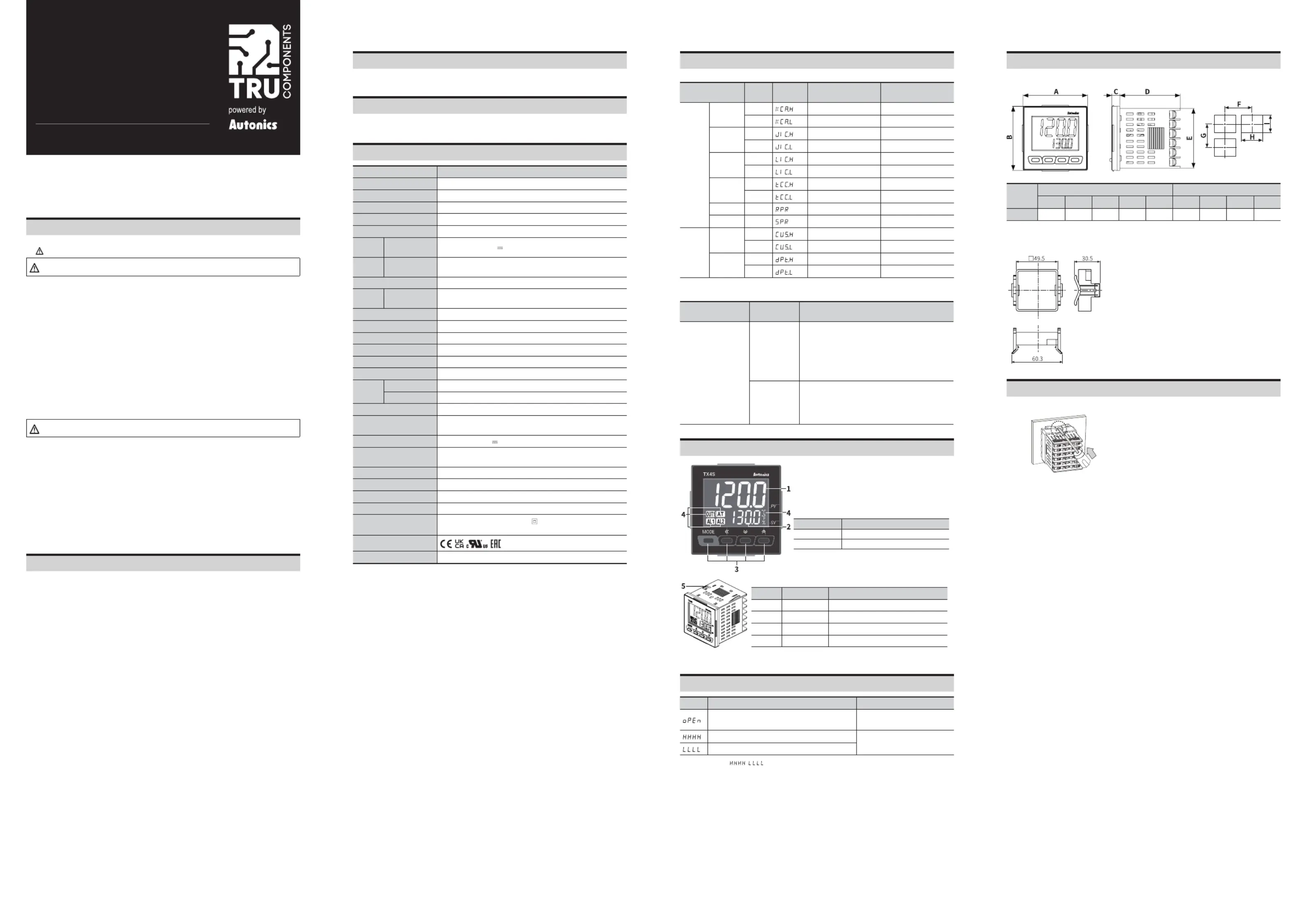
Unit Descriptions
1. PV display part (White)
•Run mode: displays PV (Present value)
•Setting mode: displays parameter name
2. SV display part (Green)
•Run mode: displays SV (Setting value)
•Setting mode: displays parameter setting value
3. Input key
DisplayName
[MODE]Mode key
[◄], [▼], []▲
Setting value control key
4. Indicator
DisplayNameDescription
°C, %, °FUnitDisplays selected unit (parameter)
ATAuto tuningFlashes during auto tuning every 1 sec
OUT1Control outputTurns ON when control output 1 is ON
AL1Alarm outputTurns ON when each alarm output is ON
5. PC loader port: For connecting communication converter (sold
separately).
Errors
DisplayDescriptionTroubleshooting
Flashes when input sensor is disconnected or sensor
is not connected.
Check input sensor status.
Flashes when PV is higher than input range.
01)
When input is within the rated input
range, this display disappears.
Flashes when PV is lower than input range.
01)
01) Be careful that when / error occurs, the control output may occur by recognizing the maximum or minimum input
depending on the control type.
Dimensions
•Unit: mm
■Panel cut-out
BodyPanel cut-out
ABCDEFGHI
TX4S484844.8≥ 65≥ 65645
45
+0.6
0
45
+0.6
0
■Bracket
TX4S
Installation Method
■TX4S
Flathead screwdriver
After mounting the product to panel with bracket, insert the unit into a panel, fasten the bracket by
pushing with tools with a flathead screwdriver.
LCD PID Temperature Controllers
TX4S-14R
Item no.: 3016145
INSTRUCTION MANUAL
TCD230032AA
Termékspecifikációk
| Márka: | Tru Components |
| Kategória: | Grillplaat |
| Modell: | TX4S-14R |
Szüksége van segítségre?
Ha segítségre van szüksége Tru Components TX4S-14R, tegyen fel kérdést alább, és más felhasználók válaszolnak Önnek
Útmutatók Grillplaat Tru Components

18 December 2024
18 December 2024
18 December 2024
26 Augusztus 2024
26 Augusztus 2024
26 Augusztus 2024
26 Augusztus 2024
26 Augusztus 2024
Útmutatók Grillplaat
Legújabb útmutatók Grillplaat
9 Április 2025
7 Április 2025
7 Április 2025
6 Április 2025
6 Április 2025
6 Április 2025
5 Április 2025
4 Április 2025
4 Április 2025
3 Április 2025